The use of testable backflow preventers has been documented for more than 100 years. The Journal of the New England Water Works Association reported the evolution of the double check valve in the early 1900s. At the turn of the last century, the Journal stated that eight check valves were installed in series between the city and auxiliary water supply, yet backflow continued. The check-leakage problem was resolved when it was determined that metal-to-metal seating of checks would not seal due to corrosion. The solution was to have either the check or seal designed using a soft material, like leather.
That was a turning point toward backflow preventers as we know them today. A double check valve assembly 100 years ago consisted of two checks, two shutoff valves and test ports with gauges attached at the inlet and outlet of each check. A technician was required to inspect the assembly by reading the gauges to determine if a pressure drop existed across a check (check closed) or if the pressure was equal (a check failure existed).
Relief Valve: A Key Addition
In the early 1940s, the concept of incorporating a relief valve into a double check valve assembly was patented. The purpose of the vent was to allow any fluid flowing back through the system to exit the piping system before entering the public supply.The relief valve is designed to sense water supply pressure and the pressure between the two check valves. Supply pressure forces the relief valve closed, but pressure between the two checks (zone pressure) opens the relief valve.
The inlet check valve of a double check valve assembly is required to close with a 1 psi pressure drop. This suggests that if the supply pressure were 60 psi, the zone pressure would be 59 psi. The relief valve sensing a 1 psi difference would be spitting water with a minimal line pressure fluctuation.
Therefore, in the case of a double check valve with a relief valve-now known as a reduced pressure principle assembly (RP)-the inlet check valve loading is increased to provide a minimum pressure drop of 5 psi. This pressure drop, which is also known as a zone of reduced pressure between the two check valves, compensates for intermittent pressure fluctuations that the relief valve senses on the supply side.
The relief valve is typically designed with an elastomer seal to a metal valve body. With time, the elastomer may adhere or bond to the metallic surface, reducing the chance of opening if needed. To compensate, the RP incorporates a loaded spring to push this valve off its seat.
Because of the mechanical advantages of the RP, the industry considers this assembly appropriate for potential high-hazard or toxic applications that may be subject to backpressure or backsiphonage. It is important to remember that any backflow preventer considered appropriate for high-hazard applications may be used for low-hazard applications as well.
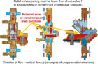
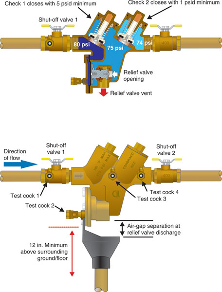
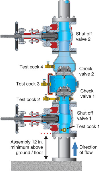
Figure 1. RP Installed Vertically
Installation Concerns
Before discussing specific code requirements associated with the RP, it is very important to state that more than 90% of RP assembly failures occur at new installations. The supply piping to the RP is not adequately flushed, and construction debris and dirt are flushed into the seat of the inlet check valve. As the check is held open with foreign material, the relief valve does not sense a pressure drop-and the relief valve spring pushes the valve off its seat, causing a venting or discharge.The plumbing code provides very basic installation requirements for the RP. However, there are other important issues to address.
Reduced pressure principle assemblies must be installed at least 12 inches above the surrounding ground or floor. This minimum requirement is not an operational limitation of the assembly. It is primarily for technician access for testing and repair. The Uniform Plumbing Code (UPC) provides that an assembly installed more than five feet above the ground or floor must be provided a platform for technician access. The International Plumbing Code (IPC) requires a backflow preventer to be accessible in accordance with the manufacturer's installation instructions.
The RP must not be installed in a vault or pit or any structure where the assembly could be submerged. Both the UPC and IPC prohibit test cocks from being installed underground. Once a relief vent or test cock becomes submerged from an underground installation, it is a cross connection.
Can an RP be installed in the vertical orientation? The answer to the question is: It is acceptable for an RP to be installed vertically, provided the assembly has been tested and approved for the vertical orientation (see Figure 1). Nearly every RP is tested in the horizontal orientation in the laboratory. Very few valves are tested in the vertical orientation with flow up or down. A restrictive specification for a vertically installed RP requires that the relief valve opening be lower than the lowest point on the inlet check valve. The relief must drain the zone between the two check valves.
If a backflow event occurs with a fouled outlet check valve, a contaminant will discharge through the relief vent opening. With a check valve at a lower elevation, the contaminant will pool at the check's outlet. If this inlet check is fouled also, the contaminant could pass through to the supply piping.
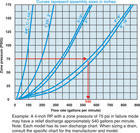
Figure 2. Relief Valve Discharge Chart
The RP is designed to discharge water with either a loss of supply pressure or backpressure through a fouled second check valve. The flow rate through the vent (relief port) can be significant, and if the discharge is not considered, a catastrophe could result. Picture in your mind a 4-inch RP installed below grade in a building's ground-level mechanical room (see Figure 2). If the supply pressure were a typical 75 psi, a failure of the first check valve may allow a discharge of 550 gallons per minute. A typical building drain will not accommodate that flow, and the result may be an industrial-sized swimming pool.
Most RP inlet check failures can be determined by a distinctive "
Cutaway of an RP
If an RP failure occurred, the 2-inch discharge pipe from the 4-inch assembly mentioned above would not gravity-flow 550 gpm. The waste is now pressurized, causing a backup in the assembly. If the checks are fouled, a backflow event will occur. It is essential to maintain the physical air gap at the relief valve discharge.
In addition to providing for any possible discharge from an RP, the designer must also consider the water quality discharged. If the inlet check valve is fouled, it's likely that the water collected for waste will originate from a potable source. However, if the discharge is backpressure backflow from process piping, such as a plating facility, the discharge could seriously impact the sanitary sewer and treatment system. Consideration must be given to the discharge being piped to an industrial pretreatment facility.
The plumbing codes provide that backflow preventers shall not be installed in areas that contain toxic fumes. If there were a loss of supply pressure with the first check fouled, the toxic gases could be aspirated into the piping system. This is a cross connection.
Double Check Valve Assembly
Finally, there's the extremely important issue of water system security. Test cocks on a backflow preventer allow the potable supply to be vulnerable to intentional contamination. Consider the consequences of a chemical tank, pump and hose being attached to the inlet or supply side test cock. Chemicals could be added to the downstream test cock also. With the correct mix of added chemicals and industrial chemicals downstream, disastrous results could occur.
All testable backflow preventers should be located in a secured area or be provided with available valve-locking devices to prevent unauthorized use.