
Figure 1. These newly constructed buildings in Europe include siphonic roof drainage systems. Photograph courtesy of Ross ADT™.
Plumbing engineers, architects, end-user clients and contractors across the U.S. are realizing the many benefits of using siphonic roof drainage. This feature attempts to enhance your knowledge of why you would choose siphonic roof drainage, how it works and how you go about designing and specifying such a system.

Figure 2. A unique roof design that features a siphonic roof drainage system. Photograph courtesy of Ross ADT™.
History
Siphonic roof drainage is a proven technology originating from Europe. The principle of siphonic roof drainage was first developed by the Finnish engineer Ovali Ebeling in the late 1960s. The first major commercial installation was in conjunction with Per Sommerhein in a Swedish turbine factory in 1972. From those beginnings, continuous research and development (again in Europe) have led to the technology becoming widespread throughout the world. In many countries, siphonic drainage is the norm for draining large roofs, and traditional gravity systems are the exception. The latest siphonic roof drainage systems feature the most up-to-date technology available for draining water from roofs, offering a combination of sophisticated, robust, well-proven roof drains together with user-friendly and accurate analytical design software programs. Using proven technology (roof drain and design software), siphonic roof drainage offers many advantages to the construction project and the end-customer.Although siphonic drainage is ideally suited to drain "big sheds,"
Figure 3. A siphonic roof drain. Photograph courtesy of HydroMax™.
The Theory of Siphonic Drainage and the Benefits
The basic theory behind siphonic roof drainage is simple. The concept is to utilize the full-bore capacity of the pipework. The piping is empty before a storm event. To eliminate further air ingress to the pipework, the siphonic drain will use an air baffle and anti-vortex device to channel water without air into the piping below (Figure 3).Acceleration of the water dropping down the vertical downpipe or leader creates a negative pressure at the highest point in a similar way to the action of a simple siphon, such as would be used to drain a pond or aquarium. This negative pressure is harnessed to draw water along a horizontal collector pipe, reducing the need for as many vertical downpipes within the building. This gives a number of benefits compared to a gravity solution:
- Underground drainage within the building footprint can be virtually eliminated, and external underground drainage piping and pipe trenching can be reduced significantly, leading to reduced costs and enhanced construction program.
- Pipe sizes are smaller than with a gravity system, reducing costs and loads on the structure.
- Significantly fewer vertical downpipes (leaders) are required, which frees valuable building floor space.
- The collector pipe runs completely horizontally without pitch, allowing the whole building space to be utilized, and making coordination with other building services and the structure much easier (pipework with no slope can be located to run through cored holes in structural beams).
For sites with a requirement for a sustainable drainage or water-recycling solution, siphonic drainage will allow water to be delivered to a specific point on the site at a shallow depth. This can significantly reduce the cost by eliminating deep trenching and other costs.*
Water is collected from the roof through specially designed drains into small diameter pipes called "tailpipes."
Cost Benefits
Cost benefits vary depending on project size and complexity, but can range from approximately 35% savings on a big box shed using solid wall Schedule 40 PVC piping, up to 65% on a warehouse with no-hub cast iron.Other suitable piping systems include Schedule 10 galvanized mild steel with roll groove joints, stainless steel and copper.
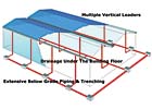
Figure 4. A typical gravity drainage piping design. Diagrams courtesy of HydroMaxTM.
Important Factors in Design
Although the basic theory is simple, when more than one roof drain is connected to a common collector main, the hydraulic calculations become very complex. This is why in practice it is necessary to utilize a proven analytical design program to complete the calculations. The most advanced design programs complete the calculations in milliseconds, even on the most complex systems.There are many very important factors to consider when designing siphonic roof drainage systems, including the following:
- The system must be carefully balanced, such that the friction losses in the pipework ensure that the correct amount of water passes through each drain, thus preventing any drain emptying that would admit air into the system and break the siphon. In practice, this is achieved by reducing the diameter of the tailpipes closest to the downpipe, and increasing the diameter of those further away.
- The suction pressures within the system must be designed so that the peak negative pressure in the system is within the capability of the piping system and above the threshold where cavitation (air coming out of suspension in bubbles) occurs. To ensure this safety, the software program parameters are set for pressures to be maintained above -26 ft (-8 m) water column. To accurately assess the pressures at points within the system, the analytical design program will evaluate friction losses within the pipe lengths, bends and junction losses, as well as the effects of velocity at nodes between every component in the system.
- The system must fill quickly enough (or prime as it is known) to operate within the design storm. The most advanced software programs identify the system prime time to ensure that this falls within acceptable limits. The only exclusion to this would be where storage on the roofs is acceptable, and thus, the system does not have to function as quickly.
Another benefit with siphonic drains is that if storage or reduced discharge is required, siphonic roof drains can be utilized as controlled flow roof drains.
Engineering of Siphonic Systems
It is necessary for the plumbing engineer to fully understand how to design siphonic roof drainage systems. The hydraulics are known and understood by professional plumbing engineers, therefore the appropriate training will be based on understanding how the hydraulics perform, particularly in relation to siphonic systems and how the parameters are met to ensure a safe, optimized design solution.Many articles have been written in the U.S. that confirm that the leaders in this technology are European-based manufacturers. This expertise has been used to develop the tools and the products that now let the U.S. plumbing engineers utilize their own skills and play their very important role in taking the many benefits from these engineered systems to their U.S. clients in the construction market.
Proven design software that is tailored for designs using traditional U.S. piping products is currently available for U.S. engineers in various formats, including windows-based desktop versions and Internet platforms, which make for speedy reliable access. These latest software developments make for easy market access to the programs and training for professional engineers in the U.S.
Analytical Design Software Programs
Because of the complexities of the design calculations, it is essential to use an established and proven analytical design program.The programs are designed to calculate head losses and pressure variations in a siphonic roof drainage system and can be used to optimize the design for new systems using proven hydraulic equations (Bernoulli, together with Colebrook-White equations calculating energy losses from piping lengths, and losses from fittings using Darcy's equations).
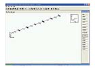
The most modern software tools require the design engineer to input the required pipework configuration into the software. The input is built graphically out of standard piping components that will mainly be at 45 degrees to each other. Fittings for bends, junctions and size changes will be added automatically by the program as required. Once built, the pipework can be autosized and manually edited (Figure 6).
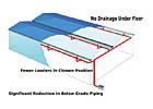
PG 38: Figure 5. A typical siphonic drainage piping design. Diagrams courtesy of HydroMax™.
System Design Checks
It is important for the design software program to produce accurate calculations and work within safe parameters. Therefore certain system checks are built into the software programs. The following system checks are made by the HydroTechnic analytical design program.- 1. Out of balance head. The difference in head range between the roof drains on the system, which should be as close as possible to zero.
- Residual head at each roof drain. This should be as close as possible to zero for the design flow rate. Residual head values above zero are not allowed because this would mean a lack of capacity. The setting shows the maximum allowable negative residual head, which indicates spare capacity.
- Maximum velocity. Excessive velocity could lead to pipe damage from erosion or cavitation.
- Minimum velocity. Ensures flow velocity remains sufficient to promote self-cleansing and prevent sediment from being deposited within the piping systems.
- Discharge velocity. This gives the discharge velocity, which enables the coordination between siphonic and belowground gravity drainage interface to be made compatible and prevent operational problems with the underground drainage system that is receiving the flow from the roof.
- Minimum pressure in the system. Excessive low pressure will lead to problems of cavitation and can cause the pipe to implode. Therefore, the parameters are set to a safe pressure rating for the piping system.
- Maximum pressure in the system. Positive pressure within a system is rare, but this is an added safety feature to ensure the maximum pressure in the system does not exceed the pressure rating for the pipework.
- Fill Time. If the laterals are too large in comparison to the capacity of the tailpipes, then the lateral will take a long time to fill with water, and hence, take a long time to develop the onset of priming. An advanced feature of the HydroTechnic analytical design program is that it calculates the pipework volume and then assesses the length of time it takes the pipe to fill if only the tailpipes are running siphonically. Computer programs like this ensure that the prime time is short and the system will be fully operational under a high-intensity, short-duration storm. It is recommended that prime time should not exceed one minute.
Common Piping Considerations
Tail PipesTail pipes run from the connection to the roof drain to the horizontal collector main. Tail pipes should not expand in the vertical if at all possible, to ensure the system fills and "primes."
* (The HydroMax™ Siphonic Roof Drainage system has a listing in the GreenSpec® directory and can be utilized to gain LEEDs point advantages, including the link to water recycling, reducing ground disturbance, reduction in raw materials, etc.)