Issue: 10/04
There are many factors to consider when designing a sewage or sump pump system. By looking at proven guidelines and common pitfalls, an economical, trouble-free system can be commissioned.
Basic Components of Sewage and Sump Pump Systems
Sewage and sump pump systems are typically composed of two or more pumps, a wet-well/basin with cover, level controls and motor controls. The model plumbing codes require two or more pumps to provide for maintenance on one pump. When multiple pumps are installed, the pumps are sized to handle the entire expected flow with one pump out of service.
The wet-well/basin can be concrete, fiberglass, ductile iron or coated steel. Concrete wet-wells can be poured in place, or reinforced concrete pipe can be used. Concrete is porous and will leak if not coated with a waterproof membrane. Older basins without waterproofing will show that the concrete has crumbled, leaving the steel rebar exposed. Fiberglass, ductile iron and coated steel limit groundwater infiltration to the wet-well. By using a fiberglass or coated steel basin, the system can be shipped to the jobsite with the piping, conduit couplings and other peripheral items already installed. Ductile iron basins are not commonly used anymore due to the closing of many foundries. Level control is typically achieved by simple float switches that tip with changing wet-well levels. Motor controls should include thermal protection for the motor.
Basin Sizing Information
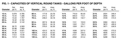
A basin should be sized to accept maximum flow with enough storage to keep the pumps submerged below the lowest inlet invert and keep the cycle times for each pump to four to six times per hour during peak demand. The diameter of the basin should be balanced with the depth based on physically fitting all components in the basin and volume of storage.Basin Sizing Example
Two 4" pumps sized to handle 80 gpm at peak inlet flow will fit into a 5' diameter basin. A 5' diameter basin has 147 gallons of storage per foot of depth. To prevent the motors from overheating, the pump motor should run for two minutes or longer.80 gpm x 2 minutes/147 gal/ft = 1.09 feet of storage required
The basin bottom will be 1.09 feet plus pump height lower than the lowest invert for this example. The worst-case design is to assume that one pump is out of service.

Types of Pumps
Self-priming, submersible and vertical column pumps have all been used for sewage and sump applications over the years. Self-priming pumps offer the advantage of being located out of the wet-well for easy maintenance. Submersible pumps with lift-out systems are also used and allow for a below grade/finished floor installation. Vertical column pumps are slowly being phased out of specifications due to the bearing trouble experienced over the years. The bearings are in the wet-well, and it is difficult to ensure that they are actually getting grease.
Basement/Inside Applications
Basins inside of building basements can be supplied with a simple steel cover that allows for mounting of pipes, vents, controls and access plates. A typical duplex self-priming pump system for sewage or sump duty is easy to unclog if large debris gets stuck inside the pump. Submersible pump systems are good for deep wet-wells. Even for sump duty, a non-clog solids-handling impeller is recommended, as debris can make its way into these pits.
The National World War II Memorial in Washington, DC, utilized a packaged sewage system in the handling of the sewage for the public restrooms. The WWII Memorial is located at the reflection pool between the Washington and Lincoln Memorials. With two self-priming pumps and controls mounted on a common skid, the entire system was able to be factory-tested for performance and integration. Site installation of the system was also simplified, allowing the contractor to mount the skid, attach piping and bring a single power feed to the control panel.
Level Control
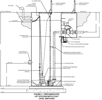
There are two types of level controls that have been demonstrated to provide minimal problems. One is a mechanical float ball with rod and mechanical alternator, generally used on indoor applications. The other is a multiple float switch system with an electrical solid-state alternator. More precise control is done using a transducer of some type. Submersible transducers with an anchor are very reliable. It is important to keep the level controls away from the wet-well inlet and the pump inlet to prevent inaccurate level readings or float failure. If turbulent water is expected or experienced inside the wet-well, a stilling well consisting of a PVC pipe can be used to protect the level controls.
Motor Controls
Controls for pump systems are often minimized in their importance. In reality, they are one of the most important components of a sewage and sump system. For submersible motors, providing a seal failure alarm can mean the difference between a simple mechanical seal change or an entire motor rewind. With a double mechanical seal on submersible pumps as standard, if the first seal fails, the motor continues to be unaffected. Many manufacturers of submersible pumps use a hardened face on the primary seals and standard faces on the secondary seals. When the alarm signals a mechanical seal failure, the pump should be serviced as soon as possible to prevent water from entering the motor through the secondary seal.
For larger pumps and motors, bearing temperature sensors should be utilized to catch bearing failures before the pump or motor experiences major failure. As mentioned earlier, the number of starts per hour on a motor should be limited to six. This is adjusted by the distance between the off and on levels set in the wet-well. The second pump should be started on a high level, along with an alarm to prevent flooding. If the high water alarm activates on a regular basis, the design professional should take a closer look at the system. This would include checking for infiltration into the piping or the basin. Also, check for new water sources. If the flow required is increased, then the pumps should be replaced with larger size pumps.
Outside Installations
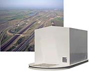
When space requires basins to be located outside of the building, self-priming pumps and controls can be located above the wet-well in a weatherproof enclosure, or submersible pumps can be used with a weatherproof control enclosure.
The Union Pacific Bailey Yard in North Platte, NE, utilized a prefabricated sewage system to meet a tight schedule of 12 hours to remove the old system and install the new system. Incorporating a basin cover into the housed sewage system base eliminated the need for the contractor to have to encase the access hatch in concrete. As a result, the installation was successfully completed in the allotted time. The station handles all the sewage that comes from the entire facility. The Bailey Yard is the nation's busiest train yard. Included in the system were two 6" self-priming pumps, a smart control that recognizes and compensates for float malfunctions, two heaters, a motorized intake louver and an exhaust fan.
Specialty Considerations
Some sump and sewage applications can pose special considerations. Recessed impellers are recommended for jails, prisons, hospitals and other sites where unusual solids are possible. Guide rail lift out systems for submersible pumps can be used to allow for easy maintenance on the pumps. Where surging or minimizing basin depth is a priority, variable speed controls can maintain a relatively constant wet-well level.A reason to minimize wet-well depth was encountered on a project for Soldier Field in Chicago. Because Lake Michigan is so close to the field, the structural engineers determined that the storm water collection basins could not be excavated to a level in excess of seven feet below the floor slab. This barrier made the design of the reservoir and pump system a huge challenge. The system had to handle flows as high as 5,000 gpm. By helping to design the wet-well inlet and utilizing large intake bells, surface vortices were prevented. Wet-well approach velocities and pump inlet velocities were kept below two feet per second to prevent other pump suction problems, such as swirling. Energy-saving variable frequency drives and smart controllers were used to maintain a one-foot differential in the water level inside the wet-well. The controller continuously adjusts the speed of the pumps in direct correlation to the wide variation of inflow rates. These rates are supplied to the controller by a submersible pressure transducer installed in the wet-well.
Sump and sewage packaged systems are often a part of a building design due to the valuable main floor spaces. To keep lower levels dry and evacuate sewage from a building, the proper design of sump and sewage pump systems is extremely important. Taking a few simple steps and asking the right questions can result in long, trouble-free removal of groundwater and sewage water from buildings.