
Issue: 4/05
When natural gas is the preferred source of energy for domestic water heating in high-rise buildings, the static pressure of the proposed hot water distribution system will exceed the maximum relief valve pressure setting of 150 psi for the listed T&Ps required at the water heating equipment. Therefore, a rooftop location for the equipment offers many long-term economic and design benefits. With a rooftop location:
- Gas pipe is cheaper and smaller in diameter than flue pipe, returning square footage to the architectural floor plans and providing a construction cost savings.
- Longevity of the water heating equipment is increased by the reduction of the operating pressure at the equipment, from near 150 psi for a basement location to approximately 25 psi for a roof location.
Buildings that require multiple water pressure zones to limit useable water pressure at plumbing fixtures to the code-required maximums, and that also require circulated return systems from domestic hot water distribution risers, present a unique design challenge. The problem here is to "centralize"
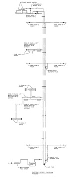
Air Relief
A major cause of poor performance in hot water return systems is "air binding,"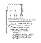
Pipe and Pump Sizing
VelocityWhen copper piping is the likely choice for return system piping, the designers should observe the Copper Development Association maximum velocity recommendations to prevent pipe wall erosion:
- 6 feet per second for domestic cold water.
- 5 feet per second for domestic hot water.
- 4 feet per second for hot water return.
An important point should be noted here. If the designer selects pipe sizes for domestic hot or cold water distribution systems with the fixture unit and Hunter's Curve method, near or in excess of the maximum velocity recommendations, the pipes will still only experience the erosive effects of excess velocity at the times of intermittent peak demand within the system. Whereas in the return system, when pipe sizes are selected from gpm flow rates at an excessive velocity, the system piping experiences the erosive effect continuously as long as the return pump runs. A constantly running return system with pipe sizes that do not strictly observe the maximum four feet per second recommendation will present pipe wall erosion and leaks in as little as two years when type "L"
Piping Friction Losses and Return Pump Head
Using gauge-reading flow control devices to accurately set minimum flow rates from each riser and within each piping segment that joins the central return system allows accurate estimation of the friction losses in return piping, predictable piping circuit flows and direction, and selection of pipe sizes that are not erosive.It is necessary to use the static head calculation formula (2.31 ft./hd. = 1 psi or 1 ft./hd. = 0.433 psi) to estimate the inlet and outlet pressures at zone connection points that utilize remote pilot PRVs. Remember to include the accumulated flows in piping segments to the PRVs to properly size the remote pilot PRVs.
The selection of the net discharge head of the hot water return pump can be figured as the total static head and friction losses of the pump discharge piping from the pump to the rooftop water heating equipment. This includes all valves, fittings and the head loss of the remote pilot PRV used to blend the return pump discharge pressure back into the domestic cold water supply to the water heaters, but minus the net positive suction head (NPSH) available at the return pump suction flange location, from the accumulated returns above.
The NPSH available at the suction flange of the return pump can be calculated from the outlet pressure of the last remote pilot PRV location, adjusted by the static head formula for elevation, minus friction loss of flow in the piping segment to the suction flange.
An overestimated discharge head selection for the hot water return pump without a control device in the pump discharge piping will allow the pump to "run wild"
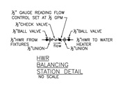
Gauge-Reading Flow Control Devices and Check Valves
Control of the flow quantity and direction at each riser through simple manually adjusted and set ball valves or square head cocks is another key to successful system arrangement. Systems that fail to predict and control flows in piping segments will likely short-circuit and take "the path of least resistance"Hot Water Return Pump Location
It is not likely that the system will be able to use a quiet running 1,150 or 1,750 rpm motor. The required low gpm vs. high discharge head pump will probably require a noisy 3,500 rpm motor that can be costly to mask or conceal. It will need to be located in nonresidential areas or with other mechanical equipment to avoid creating a disturbance in tenant areas.Consideration and application of the design points discussed here will assist in establishing problem-free installations of centralized hot water returns from multiple water pressure zones, and will provide the most flexibility during balancing, adjusting and commissioning of the system.


