
A standpipe system is a system of pipes, hose connections, valves and accessories used to supply water for manual fire fighting. Before we review the requirements, let's differentiate between a standpipe system and a hose station system.
A standpipe system is required by one of the model building codes or NFPA 101 based on the height and occupancy of a building. It can be used by the building occupants for incipient level fire fighting, by the fire department or a combination of both. The required water flow is determined by the system classification in NFPA 14, Standard for the Installation of Standpipe and Hose Systems.
A hose station system is typically required by NFPA 13 in a storage area. It is used by the building occupants for manual fire fighting, or for overhaul and mop-up operations after the fire is extinguished, and it has lower water flow requirements. This system was previously associated with the NFPA 231 series of standards for storage. These requirements have been moved to NFPA 13.
This article will focus on standpipe systems. The basis for the article is the typical questions that I have received regarding standpipe systems.
What the Codes Require
The International Building Code (IBC), NFPA 5000 and NFPA 101 will require a standpipe system based on the occupancy and height above or below the elevation of exit discharge. The requirements for when these systems are required are in different chapters or sections in each building code. The standpipes can be required because of a specific occupancy, height or number of stories. The model building codes, NFPA 101 and NFPA 5000 all reference NFPA 14 for more information. Basically, the building codes have the requirements for when the standpipes are required, and NFPA 14 provides the requirements for how the standpipes are installed (building code/when-standard/how).There has been a significant change in the IBC. The older model codes had installation requirements and definitions that were different from NFPA 14. The IBC references NFPA 14 for the design and installation of the systems. This eliminated conflicts between the code and standard, and between many building and fire departments as well.
The IBC utilizes the same system classifications as NFPA 14:
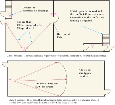
- Class I-A 2-1/2-inch (64-mm) hose connection for use by the fire department or those trained in the use of large streams.
- Class II-A 1-1/2-inch (38-mm) hose station used primarily by building occupants.
- Class III-A 2-1/2-inch (64-mm) hose connection with a 1-1/2-inch (38-mm) hose station. The large connection is used by fire departments, and the hose station by the building occupants.
The building codes and NFPA 101 will indicate where the hose connections and hose stations should be installed in a building. The requirements between the building codes and NFPA 14 are very similar, but the IBC has separate requirements for Class I, II and III systems (Figures 1 and 2).
In addition, the IBC contains sections on the requirements for protection of piping, interconnection of piping, cabinets for the hose connections and hose stations, dry standpipes, valve supervision and requirements during construction. When the IBC is used for the design, these sections should be consulted, because there are some differences between the IBC and NFPA 14.
Hose connections and hose stations are two terms that are used in the IBC, but are defined in NFPA 14 as follows:
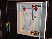
- Hose connections allow for the connection of a hose line to the standpipe system. They include a hose valve with a threaded outlet. NFPA 14 requires National Standard hose threads in compliance with NFPA 1963, while the IBC requires the hose thread to be compatible with the local fire department hose threads. There are fire departments that use hose threads other than the National Standard.
- Hose stations are a combination of hose rack, hose nozzle, hose and hose connection. A Class II and III system shall be equipped with not more than 100 feet of 1-1/2-inch collapsible or non-collapsible fire hose attached and ready for use. The hose can be in a closet, cabinet or hose rack.
If there are conflicts in these basic requirements, such as the location of the hose connections and stations, the local ordinance has to be consulted. If the local ordinance adopts the International Building Code, the IBC requirement will rule no matter which requirement is stricter.
Standpipes and Branch Line Piping
After it is decided whether the systems are required, and the system classification and locations of the hose connection are determined, NFPA 14 is consulted for the type of pipe, hangers, water flow and pressure requirements and system accessories needed.Let's look at some specific questions regarding the standpipe design requirements in NFPA 14.
The term standpipe is defined as the vertical portion of the system. A standpipe can be horizontal if it serves two or more hose connections. The branch line piping is typically horizontal piping. These terms are used when applying the system requirements such as water demand.
The flow rates for the standpipe systems are based on the class of the system. The systems can be designed hydraulically or by using the pipe schedule method. The pipe schedule method can be used for wet standpipes that are not in a high-rise application.
The minimum pressures are 100 psi for hose connections and 65 psi for hose stations. For hydraulically calculated systems, this is at the hydraulically most remote hose connection or hose station. For pipe schedule systems, this is at the upper most hose connection or hose station.
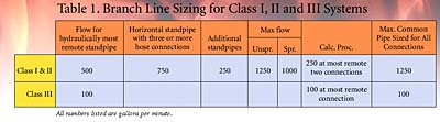
The size of the branch lines for pipe schedule systems is based on the flow and the distance from the farthest hose outlet, based on Table 7.8.2.1. The minimum size for a branch line is 2-1/2 inches. The standpipe minimum size for Class I and III is 4 inches, with a combined system minimum of 6 inches.
The size of the branch lines for a hydraulically calculated system is based on the flow, pipe size and length, with the minimum dimension of 2-1/2 inches. The minimum size for the standpipe in a fully sprinklered building with a hydraulically calculated system is 4 inches.
The hydraulic design shall comply with the requirements included in Table 1.
For a combined system (standpipes and sprinklers) for Class I and II, the larger of the flows shall be used for the system design.
The maximum pressure at hose connections for trained personnel is limited. When the pressure exceeds the code requirements, a pressure-regulating device shall be installed. The flows used are the required flows shown in Table 1. The pressure limits are a residual pressure greater than 100 psi and a static pressure greater than 100 psi for 1-1/2-inch hose connections, and 175 psi for others. When the static pressure is used, the device shall also limit the residual pressure.
The maximum flow is 100 gpm for a 1-1/2-inch connection, and 250 gpm for a 2-1/2-inch connection. The water supply for the different class system should be able to supply the flow for a minimum of 30 minutes.
Many of the system accessories and pipe requirements are the same as for a sprinkler system. This includes fire department connections, types of pipe, hangers, valves, drains, and main drains.
System Testing
The testing of the system is similar to a sprinkler system. The underground or lead-in connection has to be flushed per NFPA 24. The hydrostatic test requirements are 200 psi for two hours or 50 psi in excess of the maximum pressure for two hours.A water flow test shall be conducted by flowing water from the hydraulically most remote hose connections. The flow rate shall verify compliance with the system design. All pressure-regulating devices shall be tested with the pressure recorded on the inspector's test certificate.
The IBC does not provide a reference for a standard for the maintenance of the system, but NFPA 25 is referenced by the 2003 International Fire Code. This standard is for the inspection, testing and maintenance of water-based fire protection systems, and will provide the requirements for maintaining standpipe systems.
