Figure 1.
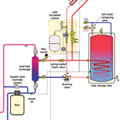
The most common type of solar thermal system uses a closed-loop circuit between the collector array and storage tank heat exchanger. In some systems that heat exchanger is located within the tank. In other systems an external heat exchanger with two circulators is used.
One characteristic of nearly all solar thermal systems is that heat production exceeds the load during warm weather. Imagine a stretch of sunny days with high temperatures of 90º F or more. The collectors are adding copious amounts of heat to the antifreeze solution passing through them. By mid-afternoon, the storage tank may be approaching 180º F. Next, mix in the possibility the family who lives in the house with this system is on vacation and thus not using any of the available hot water. It’s easy to see this scenario leading to the opening of the tank’s P&T relief valve, resulting in a basement full of steam.
Every solar DHW or combisystem (DHW and space heating) should include a method for dealing with overheating. This is especially true of closed-loop systems using glycol-based antifreeze fluids. Many systems of this type employ a method of routing surplus heat from the collector array to some type of “heat dump” where it can be dissipated to the outdoor environment.
Nocturnal Cooling
One relatively simple method of cooling a storage tank in a solar domestic water heating system is to circulate the collector loop whenever the collector temperature is a few degrees lower than the tank. In this mode, the collector array serves as a heatemitterrather than a heat collector. The system controller initiates this mode when it determines that both of the following conditions are present:A.The tank temperature is at or above a high limit setting (typically around 180º F).
B.The collector temperature is a few degrees (typically about 10º F) lower than this high limit.
Once this mode is initiated, the controller operates the collector circulator until the tank cools to a lower setpoint of around 140º F to 150ºF, at which point the heat dump mode ends. Although it may not seem to be the best way to conserve energy (thermal and electrical), nocturnal cooling is an effective way to prevent accelerated chemical degradation of glycol-based collector fluids.
Nocturnal cooling will only work in systems using flat-plate collectors. The vacuum envelope of evacuated tube collectors - the same detail thatretainsheat under desirable operating conditions - essentially prevents any significant heat loss should warm water get pumped through the tubes at night.
Diversionary Tactics
Another approach to heat dumping uses a diverter valve to reroute the hot antifreeze solution returning from the collector array once the storage tank has reached a set upper limit. The schematic inFigure 1shows this method employed to dump excess heat into a swimming pool via a separate heat exchanger.Notice that a flow switch is used to verify flow of pool water through the heat exchanger during this mode. It obviously makes no sense to pump hot antifreeze through one side of the heat exchanger without pool water flowing through the other side.
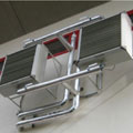
Figure 2.
Other Heat Dump Options
Not every project has a swimming pool to serve as a heat dump. Other possibilities include:- Passive fin-tube convectors;
- Fan coils/fluid coolers;
- External pavements with embedded tubing;
- Earth loops for geothermal heat pumps; and
- Automatic dumping of hot domestic water from the tank.
Each of these options has its strengths and limitations. Passive fin-tube convectors can be made from the copper fin-tube elements used in baseboards. Ideally they would be mounted in a shaded area, and such that good air circulation through the fins is possible. A typical residential fin-tube element mounted horizontally can dissipate about 250 Btu/hr. per foot of length, assuming an inlet fluid temperature 85º F higher than the outdoor air temperature.
One downside of such elements is that the spaces between fins are subject to clogging from wind-borne debris and insects. Bare fin-tube elements are also not very aesthetically pleasing, and thus would be best concealed behind a valence or mounted where appearance is not a concern.
Fan coils and fluid coolers pack more heat transfer capability into a smaller package compared to passive fin-tube elements. They do so at the expense of operating a blower. Any fan coil with a sufficient heat transfer capability could be used as a heat dump. One downside of fan coils or fluid coolers is that their blowers or fans obviously use electrical energy and thus add to the cost of system operation. They also don’t work in a power outage (unless someone manages to pack a DC motor into a fan coil and provide sufficient battery capacity to operate it).
Figure 2shows two exterior-mounted fluid coolers that serve as the heat dump for a large (nominal 1,800 sq.-ft.) collector array. Although neatly installed, this hardware adds several thousand dollars to the installed cost of the system.
Exterior pavements with embedded tubing can absorb surplus heat. Pavement areas in shade are certainly more capable than those in direct sun. A system that supplies snow melting through a heat exchanger could accept heat from the solar collector array on the primary side of that heat exchanger just as it does from a boiler during winter.
The question of using the earth loop of a ground-source heat pump as a solar heat dump often comes up in discussion. This is certainly a possibility when the heat input to the earth loop does not negatively impact heat dissipation from the heat pump operating in its cooling mode. This is a serious limitation in warm climates where heat pump systems are often operating in cooling mode.
To me this approach only makes sense in Northern climates with minimal cooling loads, or in heating-only heat pump systems. In the latter case, any heat retained by the soil around the earth loop would improve the capacity and coefficiency of performance of the heat pump. Unfortunately there is no simple way to predict how much of the potential heat input to the earth loop would be retained and later used by the heat pump. It would certainly vary from one system to another depending on soil characteristics, subsurface water movement, and time between heat input and potential heat extraction.
The option of automatic dumping of hot domestic water is effective, but may be a hard pill to swallow in areas where water is scarce or costly. If it is used, the setup is relatively simple. A solenoid valve, rated for use with domestic water, would operate based on a temperature setpoint controller. It would open at a preset upper limit temperature and remain open until the tank temperature has dropped through some differential. It is imperative that the hot water being expelled is routed to an area where it will not present a danger. Running 180º+ F water directly down a PVC floor drain pipe is not a good idea. An exterior discharge point protected from humans and pets is a better option.
Equation 1.
Sizing A Heat Dump Subsystem
To be effective, a heat dumping device must be sized for a “design” level of heat dissipation at a selected inlet fluid temperature and, in the case of convectors, a corresponding outdoor temperature. The required rate of heat dissipation will depend on the total collector area, as well as the efficiency of the collectors at design conditions.The best way to present the sizing procedure is through an example. What follows are the sizing calculations for a modest-size solar combisystem.
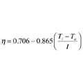
Assume the system uses 10 4-foot-by-8-foot flat-plate collectors. The efficiency equation for the collectors is on the right.
Where:
n = collector efficiency
Ti = collector inlet temperature (ºF)
Ta = ambient air temperature (ºF)
I = solar radiation intensity (Btu/hr/ft2)
Equation 2.
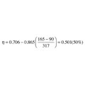
The system’s controls are set to operate the diverter valve and start the heat dumping device when the storage tank reaches a temperature of 180º F and deactivate when the tank drops to 160º F.
The least favorable operating conditions for the heat dump device will be when the tank is at the lower end of its operating temperature range. Given that there is a heat exchanger between the collector fluid and tank fluid, we will estimate the collector inlet at about 165º F when the tank is at 160º F.
The collector efficiency under these conditions is pictured on the right.
Equation 3.
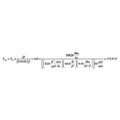
Equation 4.
The values of density (D) and specific heat (c) of the 40% propylene glycol solution were looked up for an average collector temperature of about 170º F.
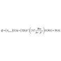
The criteria for sizing the heat dump device is thus determined as:
- Required rate of heat dissipation: 50,820
Btu/hr.
- Corresponding inlet temperature to heat dump device = 175.9º F
- Corresponding outdoor temperature = 90º F
The remaining task is to search for a device capable of operating at or close to these conditions. One example discussed earlier was a passive fin-tube element mounted outside in a shaded area. With an output rating of about 250 Btu/hr. under the above conditions, this system would require just over 200 linear feet of fin-tube element. A possible, but not probable solution. A fan coil or fluid cooler is a more likely choice for a collector array of this size.
The Achilles’ heel for many of the previously described heat dump options is that they require AC power to operate. Thus, a power outage on a hot summer afternoon still allows the collectors to stagnate, with resulting degradation of the glycol antifreeze. Although DC circulators are available that could operate from batteries, DC-powered fan coils are likely to require a custom order. This adds further complication, cost and maintenance to the system.
A Parting Thought
Drainback-type solar thermal systems do not require a subsystem for heat dumping. When the storage tank reaches a preset upper temperature, the collector circulator turns off and the water quickly empties from the collector array and goes back into the tank.Any modern collector with an OG-100 rating from the SRCC (Solar Rating and Certification Corp.) has been tested for stagnation survival and should be able to withstand “dry stagnation” conditions without damage. The collectors in a drainback system would empty during a power outage. Given the added complexity and cost of heat dumping, drainback freeze protection, especially for solar combisystems, makes good sense.


