
Last month, we looked at ways to connect two or more thermal storage tanks into an array with sufficient volume to meet the needs of a biomass boiler — or other thermal storage requirement. The key points were:
- Consider the higher heat losses of a multiple tank array, compared to a single tank of equal total volume; and
- Make a decision on whether or not each tank in the array should be capable of being isolated and removed from the system without adversely affecting the other tanks or continued operation of the system, and planning piping and accessibility accordingly.
This month we’ll look at another option, one that I personally favor, and one that’s quite a bit simpler that the scenarios we discussed last month.
Closely coupled
The piping, fittings and valves associated with parallel-direct return or parallel-reverse return piping of multiple tanks add considerable cost and complexity. One alternative that’s applicable when two or more identical thermal storage tanks are used is called “close coupling.” Two or more tanks are brought close to each other and the aligned side ports are joined using a combination of short piping segments and a suitably-rated semi-flexible coupling. Figure 1 shows an example.
Figure 1:
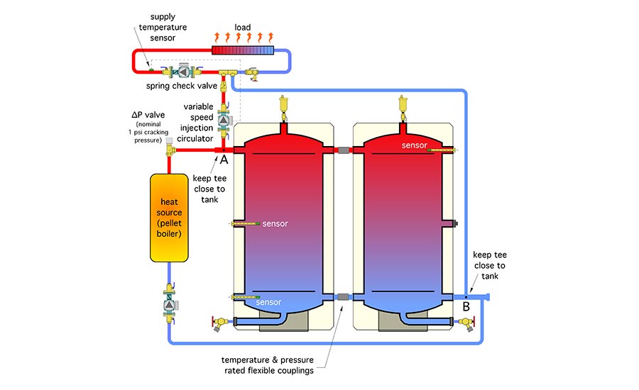
Close coupling attempts to make two or more tanks into a single entity from both a thermal and hydraulic standpoint. The “approximation” in this attempt is that the two or more thermal masses are separated by the close coupling piping connections. The hydraulic losses associated with these close coupling connections should be kept as low as possible. When this is achieved, the multiple tanks can provide the required thermal storage volume, as well as hydraulic separation of the heat source circulator and the circulator shuttling heat to the distribution system.
The two tanks in Figure 1 are also connected in reverse return relative to each other. Hot water enters or leaves the tank array at point A. Cooler water enters or leaves the array at point B. The reverse return piping helps balance the total flow rate equally between the two tanks.
If one visualizes the two tanks as a single thermal storage volume, that volume is connected in a 2-pipe configuration relative to the boiler and the load. This helps reduce flow velocity through the tanks when the load and heat source are operating at the same time.
Figure 2 shows one method of coupling two identical tanks together at their side ports.
Figure 2:
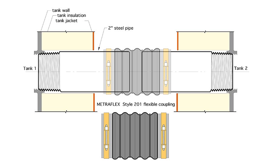
If the tank has FPT connections, a steel pipe nipple is threaded into each side port. If the tank has flanged connections, a matching flange with a short length of pipe welded to it can be used. These segments of pipe should be kept short to allow the tanks to be positioned as close to each other as possible. A slight gap should be left between the butt ends of these pipe to allow for expansion movement.
A reinforced semi-flexible coupling is used to couple these piping segments together. The coupling must have temperature and pressure ratings suitable for the application. The Metraflex style 201 coupling shown in Figure 2 is rated for 225° F and 75 psi. It’s available to fit pipe sizes from 2 inches to 12 inches.
These couplings allows for slight misalignment of the two piping segments. Please note the word “slight” in the previous sentence. This flexibility helps in situations where identical tanks are to be closely-coupled, but rest on a concrete floor slab that’s not perfectly flat. In such cases, it may be necessary to use steel shims along with structural grout under one or more of the tanks to coax them into the best possible alignment.
The “downside” of close coupling is that it doesn’t allow each tank in the array to be isolated and serviced while keeping the remainder of the system in operation. Still, the chances of having to do this are very small, and, in my opinion, acceptable given the far simpler piping and reduced installation cost.
Details are important
To achieve good performance, thermal storage tanks should be very well insulated (I recommend R-24 °F•hr•ft2/Btu as the minimum insulation requirement). This R-value can be achieved with a nominal 4-inch monolithic coating of spray polyurethane foam. Most codes will require the foam to be covered with an intumescent coating or other jacketing that provide a fire resistance rating. Figure 3 shows a 360 gallon ASME listed thermal storage tank with that insulation system — and a rather unique but carefully executed “Minion” paint job.
Figure 3:

Always pipe the tanks in ways that encourage temperature stratification. If the tanks don’t have baffles, as shown in Figure 1, avoid piping connections that create vertical flow jets inside the tank. Be sure air can be vented from the top of the tank, and always provide valving for drainage.
Multiple thermal storage tank arrays can enable renewable energy heat sources, such as biomass boilers, to be used in situations that cannot accommodate a single larger tank. However, this enablement results in higher installation cost and higher heat loss relative to single large tank application. Still, when a single tank can’t work, the strategies discussed in this column, and last month’s column, provide a workable alternative.

