Drinking water systems provide the fixtures and low temperature water used only for drinking purposes. This article describes the fixtures, design criteria and the piping distribution system used to supply and distribute chilled water to all fixtures of the system.
Applicable standards and codes are the Air-conditioning and Refrigeration Institute (ARI) Standard 1010 (standard rating conditions) and ARI Standard 1020 (standard rating criteria), as well as the local, ADA and other codes for the number and type of fixtures.
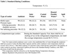
Table 1
Types of Fixtures, Accessories and Chiller Assembly
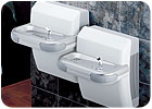
Bottled Water Unit.Bottled water units are not considered plumbing fixtures because they have no connection to any plumbing system. These units are completely self-contained and do not require any electrical connections, a piped water supply or a drain. Water is supplied from bottles, generally containing 5 gallons of water, that must be replaced when empty. Water is discharged from faucets and dispensed into cups. Spills are contained in a receptacle on the unit under the faucet and must be emptied when full.Drinking Fountains (DF).Drinking fountains are considered plumbing fixtures and are directly connected to plumbing potable water and drainage systems. Water to the unit is supplied either from a remote, central chilled water unit or ambient temperature water from the potable cold water system. Water is dispensed under pressure through a bubbler or spout and does not require a cup. Excess water that is not consumed is piped direct to the sanitary drainage system.
Electric Water Cooler (EWC).An electric water cooler is a completely self-contained plumbing fixture consisting of an integral, directly connected drinking fountain and water chilling unit serving only this unit. These units are supplied with pressurized ambient temperature water, which is chilled by the self-contained refrigeration unit. Water is dispensed under pressure through a bubbler or spout and does not require a cup. Excess water not consumed is discharged directly into the sanitary drainage system, generally through a coil that additionally cools the incoming water. If a refrigeration unit is intended to serve more than one drinking fountain, a maximum of 10' distance from the unit is recommended.
There are many different accessories and components that can be provided for many models of drinking fountains, such as glass fillers, hot water dispensers and foot pedals.
The central chilled water assembly is a mechanical refrigeration unit specifically designed to chill incoming water and distribute the chilled water to multiple drinking fountains. It consists of a compressor and condenser, evaporator, storage tank, recirculation pump and filters.
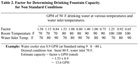
Table 2
System Design Concerns
System design involves determining the number and type of fixtures needed, system space requirements and sizing the storage tank.Regarding fixtures, the first step is for the architect to select the location of the drinking fountains. The applicable plumbing code generally has requirements for the minimum number of drinking fountains based on the amount of people served and the type of building. Additional drinking fountains may be provided for the convenience of the building occupants.
Free standing units typically require a minimum of 18" (460 mm) square, with a recess of 30" (760 mm) wide by 24" (600 mm) deep. The chiller pack for an electric water cooler requires a recess under the unit of approximately 24" (600 mm) square and 9" (230 mm) deep. The recess for the drinking fountain varies with the model selected.
The storage tank is normally sized for one half of the calculated system hourly demand. For example, if a 100 gph (380 L/hr) demand is calculated, a 50-gallon (190 L) tank would be selected. The designer should select a standard size tank from the manufacturer.
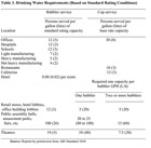
Table 3
Pipe and Insulation Sizing and Selection
The most common piping specified is copper tube, conforming to ASTM B88, with soldered joints. The pipe should be insulated with a minimum of 1-inch-thick insulation with a vapor barrier to keep the heat gain to a minimum and to prevent condensation.The maximum recommended velocity for circulating water is 3 feet per second (FPS) or 1 meter per second (1m/sec). The friction loss through the piping should be limited to approximately 10 ft. (3 m) of head for each 100 ft. (33 m) of pipe. Dead-end piping should be limited to approximately 10 ft. (3 m) in length.

Table 4
System and Component Sizing
General Criteria.Tests have shown that water at less than 50°F (10°C) is considered too cold for most people; furthermore, the flavor buds of the tongue are numbed by the cold. Based on this study, a slightly higher temperature of discharged water is considered to be appropriate.The maximum recommended pressure for any system is 125 psig (870 kPa). If the pressure is higher than 125 psig, a second zone should be established. There has been a general trend away from central systems serving many units except for buildings with cores. It is usually more economical and allows improved maintenance to use groups of four to six units served by a small chiller.
Sizing Criteria.The standard used by manufacturers for the capacity of chilled water produced from a single water cooler is based on ARI standard 1010. This standard uses an inlet water temperature of 80°F (27°C), a discharge water temperature of 50°F (10°C) with the drinking fountain installed in an area with an ambient temperature of 90°F (35°C).Table 1lists standard rating conditions for a variety of installations. If any conditions are different from the standard, useTable 2to determine a factor that will calculate the flow of chilled water at those non-standard conditions.
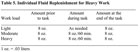
Table 5
Table 4has been developed by ARI standard 1010 and is used to find the number of people served per hour. A similar table, often found in manufacturers' literature, may also be used. There is usually a wide discrepancy between information for offices, schools and hospitals found between Tables 3 and 4. The use of Table 3 will generally result in one half the size unit than the use of Table 4. This should be reviewed and evaluated with the selected manufacturer to arrive at an appropriate figure. Experience has shown that a value of between 5 and 8 gallons (19 and 30 L) per hour for average conditions is sufficient for drinking fountains found in these areas.
Individual fluid requirements for various heavy work loads are given inTable 5. This figure should be used if necessary in lieu of any previous figures calculated. Sufficient unit capacity should be allowed for the required amount of water replenishment provided at the unit based on the number of people the unit is serving.

Table 6
Individual Unit Selection
The selection process involves the following five steps:1. Determine the number of units required from where shown on the plans, required from the code, or as established by the architect.
2. Determine the ambient environment where the units will be installed.
3. Find the specific area where the installation will be made to see if there is water, drain piping and space necessary for the style of unit to be installed.
4. Determine children or ADA requirements (for mounting height).
5. Size the refrigeration requirements for individual units based on Tables 3, 4 and 5, using judgment as to the various conditions encountered.
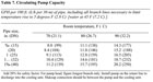
Table 7
Central Water Chiller Sizing
To properly size the central water chiller, follow these steps:1. Calculate or obtain the total number of drinking fountains.
2. Determine a single fountain usage by using Tables 3, 4 and 5, as applicable, to find the number of gallons per hour required for one unit.
3. Calculate the total water usage (makeup) for all units served by the central chiller by multiplying the figure found in step 1 by the figure calculated in step 2.
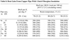
Table 8
5. Select a preliminary size for the distribution loop header. The size will be selected to reduce the friction loss in order to keep the circulation pump horsepower as low as possible. A general starting point is 1-in. (DN 100) size line. This is an iterative procedure to find the final pipe size.
6. Calculate the capacity of the chilled water circulation pump. First, select the gpm of the pump. This is accomplished usingTable 7. Using the table with the pipe size (found in step 5) and ambient room temperature, find the gpm required to limit the heat loss from the pipe to 5°F (2.8°C) at the intersection of the two figures. The actual pump selection must overcome the friction loss of the flow in the distribution loop, which can be found using a standard engineering text. Selecting the size is an iterative procedure using manufacturers’ pump curves to select a cost-efficient pump.

Table 9
8. Calculate the heat generated by the circulating pump that must be made up. UseTable 9, entering the circulating pump horsepower from the size selected in step 6.
9. Calculate the heat gain from the chilled water storage tank. Usually, 1-1/2" fiberglass insulation is selected. This thickness has a conductivity of 0.13 Btu/ft (0.4W/M). Obtain the area of the tank from the manufacturer.
10. Calculate the actual central chiller size in Btu/hr (W) by adding the results of steps 4, 7, 8 and 9. It is suggested that an additional 10% be added as a safety factor.
References
ASPE Data Book, Chapter 27, Water Coolers, 1994.
Acknowledgements
Elkay/Halsey Taylor Mfg. Co.