Figure 1.
Solar thermal systems are a growing sector of the American HVAC market. Several companies now offer “plug and play” systems for domestic water heating. Some of these companies, as well as those who design residential HVAC systems, are also looking at how “combisystems” (e.g., systems that contribute to both domestic water heating and space heating) can be implemented into existing buildings and new construction.
Combisytems can be as small as a couple of collectors - or as large as the client’s budget and roof space allow. Smaller systems contribute primarily to domestic water heating and offset some space heating during spring and fall months. As the number of collectors and storage tank volume increases, a combisystem will yield higher annual solar fractions (e.g., the percentage of the combined space heating and DHW load being met by solar energy).
As the size of a combisystem increases, its economic return on investment (ROI) decreases. Each square foot of collector area added to the system yields lower ROI than the previous square foot. This trend is easy to study with solar thermal simulation software such as f-chart (www.fchart.com).
Some residential combisystems have been constructed with massive collector arrays and storage tanks of 1,000+ gallons. The objective was to attain high annual solar fractions, perhaps even approaching 100%. Given a large roof, an even larger bank account, and sufficient “green-mindedness,” such systems are possible for unique clients.
However, the ROI of these systems makes them economically unsustainable for the general public. They may be monuments to the energy philosophy of their owners, but they do little to promote implementation of solar thermal technology to more pragmatic consumers. Such systems also create significant heat dissipation problems during spring, summer and fall, when space heating loads are minimal or nonexistent.
Are We Over
"Bigger Is Better?"
As energy prices escalate, the U.S. economy edges out of recession, and
interest in sustainable living increases, a growing segment of U.S. consumers
are looking for smaller, more energy-efficient homes. U.S. census data
indicates the average square footage of single-family homes dropped about 11% between
the second and fourth quarter of 2008 - the first such decrease in 10
years.The design of smaller, energy-efficient homes continues to be a popular topic at sustainable energy conferences, and has been brought to the forefront through a best-selling book entitled “The Not So Big House” by architect Sarah Susanka (a highly recommended read).
This trend isn’t about building homes with stucco toweled over stacked straw bales or converting tree houses into living quarters. It’s about very-well-thought-out spaces and use of durable/readily available materials versus those shipped in from halfway around the world.
It’s likely those seeking such homes also have an above-average interest in use of renewable energy. The U.S. solar thermal market could be well positioned to take advantage of this trend. But just as smaller homes require rethinking of space, solar combisystems for such homes require departure from conventional thinking.
Consider This
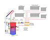
Figure 1is a schematic for a small drainback solar combisystem that could supply much of the domestic hot water and some space heating for a modest home with four occupants.The performance of this system has been simulated for a 1,500-sq.-ft. home for two locations: Albany, NY, and Boulder, CO. The simulation was based on the following system configuration:
- four 4x8-foot flat plate collectors (128-sq.-ft. gross
area)
- collector efficiency line intercept = 0.76
- collector efficiency line slope = 0.865 Btu/hr/ft2/ºF
- collector slope = latitude +15º
- collector azimuth = 180º (directly south)
- 119-gallon, well-insulated storage tank
- DHW usage = 60 gallons/day heated from 50ºF to 120ºF
The design space heating load of the 1,500-sq.-ft., well-insulated house was set at 15 Btu/hr/ft2, or 22,500 Btu/hr total, with an indoor temperature of 70ºF and outdoor design temperature of 0ºF. This yields an overall heat transfer coefficient of 321 Btu/hr/ºF.
The results of the f-chart performance simulations are shown inFigure 2.
The specified combisystem supplies almost 31% of thetotal annualspace heating plus domestic water heating load for the house in Albany, NY. The total solar fraction increases to 44% if the same house were located in Boulder, CO.
The bar graph shows that solar contribution to total load is relatively low in the dead of winter. Don’t expect miracles when the heating load is highest, and available solar energy is lowest. The solar heating fraction rises quickly beginning in March, and drops off after October. During mid-summer, the system supplies nearly all the load - essentially just domestic water heating - in either location.
These are significant solar contributions, achieved with modestly sized collector arrays and storage tanks.

Figure 2.
System Anatomy
This closed-loop, pressurized drainback system eliminates the need and expense associated with a heat dump - which is required for most antifreeze-based solar combisystems. It also eliminates several hardware components such as antifreeze, air separators, expansion tank, collector loop relief valve, top-of-loop air vent and fill valves.The storage tank in this system holds “system water” rather than domestic water. As such, it could be constructed of standard carbon steel.
The upper portion of the tank is maintained at the minimum temperature required for domestic water heating whenever that service is required. If the sun is out, it may heat the tank well above the minimum required temperature. Hence, a mixing valve is used to prevent high temperature water from going directly to the panel radiators.
During less sunny conditions, the integral condensing burner/heat exchanger maintains temperature at the top of the tank. A well-stratified tank keeps the hot water at the top, while cooler water at the tank’s bottom stands ready for circulation through the collector array when the sun returns. The thermal mass of the tank allows it to buffer the well-zoned distribution system without short-cycling the burner.
Collector flow is handled by a variable-speed circulator that turns on at full speed to establish a siphon within the collector return piping, then drops to a lower, user-selected speed to maintain flow. Because it operates at a significantly reduced speed during most of the solar collection cycle, the electrical demand of this circulator is comparable to that of a circulator in an antifreeze-based system.
The space heating distribution system consists of a single ECM-based, pressure-regulated circulator with a maximum power draw (at full speed) in the range of 40 watts. This circulator supplies a simple copper tube manifold station that connects to several panel radiators, each equipped with a non-electric thermostatic radiator valve. These panels are sized for 125ºF supply water temperature at design load conditions. The thermostat valves on each radiator allow heat delivery to automatically adjust to internal gains within each room. Unchecked, such gains can cause significant temperature variation in smaller, well-insulated homes.
The electrical energy consumption of this distribution system would be a small fraction of that required by a forced-air system of equivalent capacity and zoning configuration. It’s vital to communicate this reduction in “distribution energy” when promoting hydronics to energy-minded consumers.
Domestic water is heated instantaneously as it passes through the external stainless steel heat exchanger. A flow switch turns on the small circulator supplying this heat exchanger whenever there’s a demand for domestic hot water. Hot water from the top of the tank flows through the primary side of the heat exchanger and instantly transfers heat to the other side. This heat exchanger is easily replaceable (and recyclable) if ever necessary due to scale or other issues. The minimal quantity of domestic water residing in this heat exchanger (probably less than one pint) reduces the possibility of legionella growth.
The components shown in Figure 1 could (and should) be consolidated into a packaged product. This would speed installation and ensure proper component sizing and placement. It would also help consumers view solar combisystems as an appliance rather than a highly customized/complex system.
Is the U.S. solar industry ready to supply products tailored for smaller, energy-efficient homes? Is your firm ready to promote their virtues and install them? Perhaps it’s time to gear up. The sustainable housing market is in need of solutions.

