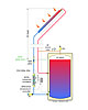
Figure 1.
In the AugustSolar Design Notebookcolumn, we discussed the difference between open-loop and closed-loop drainback systems. One characteristic shared by both is the manner in which flow through the collector array is controlled.
Both systems require a pumping system that can move water from its “resting level” in the system and push it up through the collector array. In doing so the pumping system must overcome both frictional flow resistance through the piping, as well as the vertical lift. The latter is distinctly different from the situation encountered by circulators in closedfluid-filledhydronic systems.
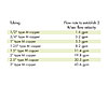
Figure 2.
A drainback system might contain two circulators in series (as shown inFigure 1), or a single “high head” variable-speed circulator. In either case, when the circulator(s) are turned on, water immediately heads up the collector supply piping. Air is pushed ahead of this water.
When the water column reaches the top of the collector piping, one of two things can happen:
1.If the water has sufficient velocity it will entrain air bubbles and eventually carry air in the return piping back to the storage tank.
2.If the water’s velocity is low, it will not entrain all the air, and there will be a mixture of water and air “gurgling” down the return line.
Both situations will move heat from the collector array to the storage tank. However, the first scenario is much preferred to the second. When properly configured, it can reduce pumping energy, pipe size and operating noise.
A “safe” flow velocity to ensure that air is entrained and carried down a vertical pipe is two feet per second. At this speed or higher, a siphon will quickly form in the return piping. Once formed, this siphon cancels out most of the initial “lift head” associated with filling the collector array.
The flow rate (in gpm) needed to achieve a flow velocity of two feet per second is listed for several sizes of copper tubing inFigure 2.
Once the siphon is established, it’s possible to turn off the upper of two series-connected circulators or reduce the speed of a single high-head circulator, and still maintain adequate flow through the collector array.
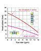
Figure 3a.
Figure 3a shows the effective pump curve of two identical fixed-speed circulators connected in series. It is constructed by doubling the head of the single circulator at each flow rate.
Both circulators are turned on each time the solar energy collection process begins. During the first few seconds of operation, water is lifted upward through the collector supply piping. This causes the system curve to migrate upward along the graph as depicted by the system curves labeled S0 through S3 in Figure 3b. These curves steepen as they rise because the flow resistance increases as water progresses along the supply piping and up through the collector array.
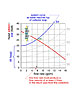
Figure 3b.
To establish a siphon, the flow rate at operating point OP1 must produce a corresponding flow velocity within the return piping of two feet per second or higher. This will quickly rid the return piping of air, moving it back to the top of the storage tank.
At that point, the water moving down the return piping helps “pull” an equal amount of water up the supply piping. Think of the water in the supply and return piping like a length of rope draped over a suspended pulley. With equal amount of rope on both sides of the pulley, the effort to move the rope is very minimal because the weight of rope on both sides is the same.
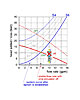
Figure 3c.
In a typical residential drainback system, this overall sequence takes 30 seconds to perhaps three minutes. Once completed, almost all of the initial “lift head” is gone. This allows the option of turning off the upper of the two circulators using a time delay. The operating point then shifts to a final position marked as OP2. This point determines the flow rate through the collector circuit for the remainder of the solar collection cycle. Even with half the pumping power, this flow rate is higher than when water first moved over the top of the collector circuit with both circulators operating. In this example, it’s about 7.2 gpm.
A similar cycle occurs in systems that use a single speed-controlled circulator. The circulator starts at full speed to quickly push water up through the collector array and establish the siphon. After a period of time, the circulator reduces its speed (based on user programmed settings). The intersection of the circulator’s reduced speed pump curve and the system curve after the siphon has formed determines the flow rate through the collector array for the remainder of the collection cycle.
Although the dual-circulator approach we’ve discussed works well, advances in circulator technology make it likely that a single, variable speed circulator - especially those using electronically commutated motors - will soon become the standard for drainback systems. They hold advantage in terms of lower installed cost, higher wire-to-water efficiency and more flexibility for different system heights and flow requirements.
Two Final Bits of Advice
1.If you’re installing a “dual-pumped” drainback system, make sure the flow direction arrows on both circulators point in the same direction before bolting them together. Don’t laugh – the opposite of this has happened more than once.2.Make sure you remove any internal check valves in the circulator(s) before installing them together.

