
In the Dec. 2008 Solar Design Notebook column, we calculated the temperature that the absorber plate in a solar collector could reach under stagnation conditions. If stagnation occurs on a hot/bright summer afternoon, that temperature could exceed 350ºF, and it’s very likely the fluid in the collector will vaporize. This has to be taken into account when sizing an expansion tank for the collector circuit. With the proper sizing it’s possible for the collector array to stagnate without causing the circuit’s pressure relief valve to open.
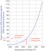
Figure 1.
To maintain this solution as a liquid at a stagnation temperature of 350ºF requires an absolute pressure of about 118 psi (with a corresponding gauge pressure of about 103 psi) in the solar collectors. This is not practical, and may even violate some mechanical codes that require the collector circuit pressure to be no higher than the pressure of the domestic water.
Thus, we can’t count on pressurization to suppress boiling under stagnation conditions. Under these conditions, the liquid in the piping leading to and from the collector array could also be very hot.
To prevent the relief valve from opening under these conditions, the expansion tank must absorb both the fluid displaced by vaporization in the collectors, as well as the expanding volume of the remaining liquid in the circuit.

Selecting the PRV
Before calculating the volume of the expansion tank, it’s necessary to know the rated opening pressure of the system’s pressure relief valve. Valves are available with a wide range of rated pressures for solar thermal applications.Start by checking local codes to see if they mandate a maximum pressure relief valve setting in solar thermal systems. If this is the case, the code-mandated rating is obviously the maximum rating the valve can have.
If there are no code restrictions, I suggest the relief valve pressure be determined as follows:
1.Assume a cold fluid static pressure of 25 psi at the top of the collector array, and then calculate the corresponding pressure at the relief valve location.
2.Select a relief valve with a rated opening pressure 15 to 20 psi above this pressure.
UseFormula 1to determine the cold fluid static pressure at the relief valve location. SeeFigure 2for the corresponding terms and dimensions.
Formula 1:

P@PRV = static cold fluid pressure at pressure relief valve location (psi)
P@top = static cold fluid pressure at top of collector array (psi)
H = vertical distance from pressure relief valve to top of collectors (feet)
0.45 = a factor based on units and the density of 40% propylene glycol solution at 50ºF
For example, assume 25 psi static cold fill pressurization at the top of the array and 22 feet of vertical distance from the top of the array down to the relief valve location. The static pressure at the relief valve location would be:
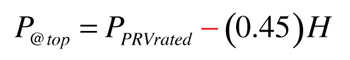
You can useFormula 2to determine the pressure at the top of the collector array just as the selected pressure relief valve is about to open (e.g., the condition we are trying to avoid at stagnation).
Formula 2:

P@top = pressure at top of collector array as relief valve reaches rated opening pressure (psi)
PPRVrated = rating of pressure relief valve (psi)
H = vertical distance from pressure relief valve to top of collectors (feet)
0.45 = a factor based on units and the density of 40% propylene glycol solution at 50ºF
In our example this would be:
The gauge pressure of 40.1 psi corresponds to an absolute pressure of 40.1+14.7 = 54.8 psi at the top of the collectors. According to Figure 1, this pressure would maintain the 40% propylene glycol solution in the collectors, as a liquid, to a temperature of about 295ºF. This temperature is higher than the fluid would experience in normal operation, but not high enough to prevent vapor formation under summer stagnation conditions.
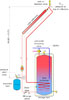
Figure 2.
Accommodating Growth
Since it’s highly likely the collector fluid will vaporize during stagnation, we will need to size the expansion tank to accommodate this expansion as well as that of the remaining liquid in the collector circuit.Step 1:Determine the volume the expansion tank must accommodate at stagnation usingFormula 3. This formula assumes vapor will form in the collector during stagnation. A small amount of vaporized fluid will create sufficient volume to push the remainder of the liquid out of the collectors. The formula also assumes the liquid temperature in the remainder of the system will reach 200ºF above the temperature at which the system was filled. This is a conservatively safe assumption.
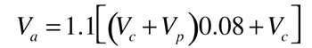
Where:
Va = expansion volume to be accommodated (gallons)
Vc = total volume of collector array (gallons)
Vp = total volume of collector piping and heat exchanger excluding collectors (gallons)
0.08 = expansion factor for 40% propylene glycol solution for 200ºF temperature rise
1.1 = 10% added safety factor to allow for system volume estimates
The fluid volume contained by a collector is usually listed in manufacturer’s specifications, as is the volume of the circuit’s heat exchanger. The volume of copper collector piping can be estimated using data fromFigure 3. If other types of tubing are used for the collector circuit, obtain volume data from the manufacturer.

Formula 4:
Pstatic = static presre at the relief valve location (psi)
H = height of collector circuit above location of pressure relief valve (feet)
0.45 = a factor based on units and the density of 40% propylene glycol solution at 50ºF
Note: The air side of the diaphragm expansion tank must be pressurized to this calculated static pressure before fluid is added to the collector circuit. This ensures the diaphragm is fully expanded against the tank shell before the fluid begins to warm.
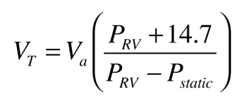
Step 3:Calculate the minimum required expansion tank volume usingFormula 5, which is derived from Boyle’s law.
Formula 5:
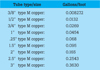
Figure 3.
VT = minimum required expansion tank volume (gallons)
Va = expansion volume to be accommodated [from Step 1] (gallons)
Pstatic = cold fluid pressure at the relief valve location [from Step 2] (psi)
PRV = maximum allowed pressure at the relief valve location (psig). I suggest this value be the pressure relief valve rating minus 3 psi. This provides a slight safety factor against relief valve “dribbling” as the pressure approaches the valve’s rating.
Here’s a final example that pulls this all together. Assume a residential solar water heating system has the following components:
Determine the minimum size of a diaphragm-type expansion tank for the system such that the relief valve doesn’t open under stagnation conditions. The cold fill pressure at the top of the system is 25 psi.

Solution:
The total collector array volume is 4 x 1.0 = 4 gallons.The total piping + heat exchanger volume is 120 ft x (0.0269 gallon/ft) + 2.5 = 5.73 gallons.
Step 1:

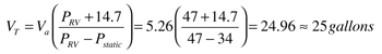
Note: The PRV value used in Step 3 was the rated valve pressure minus 3 psi to guard against “dribbling” of the relief valve as it approaches its rated pressure.
As you can see, the expansion tank for the system is significantly larger than a hydronic heating system of similar volume. This is partially the result of very conservative assumptions, and partially the result of steam flash in the collectors at stagnation. As in hydronic heating systems, a conservatively sized expansion tank is good “insurance” against the system requiring servicing following a stagnation condition.
In cases where the minimum required expansion tank volume exceeds the volume of available tanks, it is acceptable to use multiple tanks connected in parallel. Be sure the air side pressure in each tank is set to the calculated static pressure prior to filling the collector circuit.
Finally, be sure to locate the check valve in the collector circuit so that fluid can be pushed out of the bottom and top of the collectors as vaporization occurs (see Figure 2). This is an important detail to allow expedient emptying of the collector as boiling begins.

