Heat emitters play a key role in sustainable performance.
I began working in the renewable energy field in 1978 as an applications engineer for Revere Solar & Architectural Products in Rome, N.Y. At the time, Revere was one of the largest U.S. producers of flat plate solar collectors. Those collectors were sold as part of solar domestic water heating systems, as well as for “combisystems” that provided both domestic water heating and some limited amount of space heating.
In those “early days,” solar heating essentially boiled down to using solar collectors as the sunny day substitute for conventional boilers or water heaters. Designers focused on the collectors, storage and control aspects of the solar subsystem, but devoted little time to developing compatible means for distributing that solar-derived energy within the building to be heated.
The hydronic distribution systems of that era were designed around relatively high supply water temperatures. Most residential systems used common fin-tube baseboard to release heat from water sent through the piping circuits at temperatures sometimes exceeding 200ºF.
Many designers of that era discovered the relatively high water temperatures required by conventional space heating distribution systems were beyond what solar collectors could consistently produce. Sure, there was an occasional “perfect solar day” in December or January when the storage tank did get hot enough to supply the home’s heating load during the following night. But the average system performance over a typical northern heating season was often disappointing. In short, after owners invested thousands of dollars in collectors, storage tanks and other hardware, many of these early systems spent much of their time distributing heat generated by conventional fuels rather than by the sun.

|
|
Figure 1. |
It's the distribution system ... stupid
In retrospect, many designers of first-generation solar combisystems spent little time developing space heating distribution systems that were compatible with what a typical solar collector could produce.
The North American tendency to focus on the heat source rather than the system as a whole continued to limit the performance of solar combisystems. To overcome this, designers must understand the ramifications of system operating temperature on the efficiency of the heat source.
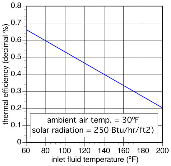
Figure 1 shows how the instantaneous thermal efficiency of a flat plate solar collector is affected by the temperature of water entering its absorber plate.
Assuming the outdoor air temperature and solar radiation intensity remain constant at the indicated values, which represent a sunny mid-winter day in a northern U.S. climate, the thermal efficiency of the collector drops rapidly with increasing inlet fluid temperature.
For example, if the fluid temperature entering the collector is 90ºF, the outdoor air temperature is 30ºF and the sun is bright (e.g. solar intensity is 250 Btu/hr./ft.2), the collector gathers about 56% of the solar radiation striking it. However, if the entering fluid temperature is 140ºF, while the other conditions remain unchanged, the collector’s efficiency falls to about 40%. That’s a significant “penalty” for forcing the collector to operate at higher fluid temperatures. It’s the result of greater heat loss from a hotter collector to the outside air, much like your heating energy use goes up if you keep your house at 75ºF rather than 68ºF.
Making it happen
Hopefully you’re now convinced that low water temperature distribution systems enhance the performance of solar thermal combisystems. My suggestion is to create your distribution systems so the supply water temperature under design load conditions doesn’t exceed 120ºF. With that in mind, let’s look at some heat emitters that love to operate under these conditions.
First, it’s critically important to understand what determines the water temperature in any hydronic distribution system.
Some designers, including an embarrassingly high percentage of HVAC professionals, think it’s the heat source that controls the water temperature in a hydronic heating system. This notion stems from the fact many boilers come with a control device that has a dial (or perhaps digital interface) on which the installer “sets” a water temperature. Many think by setting this temperature they are “guaranteeing” the heat source will produce it. This is not the case. The set temperature is only a limit on how high the water temperature leaving the heat source might climb.
The water temperature in any hydronic distribution system only climbs high enough for that system to achieve thermal equilibrium - where the rate of heat release from the distribution system exactly balances the rate of heat input from the heat source. Once this condition is achieved, there is no “thermodynamic incentive” for the water temperature to climb higher, and it won’t!
It’s the design of the hydronic distribution system, including the selection and sizing of the heat emitters, that determines the water temperature at which the system will operate.
Anyone who designs a heating system wants to maximize its thermal efficiency. Today, that means moving away from high water temperatures by specifying heat emitters with larger active surfaces, or other details that increase both convective and radiative heat transfer. This allows thermal equilibrium to occur at relatively low water temperatures during both maximum load and partial load conditions.
|
|
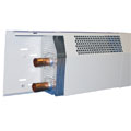
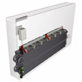
Figure 2. Photo courtesy of Smith’s Environmental Products |
Emitter evolution
There are several ways to design modern hydronic distribution systems around the low water temperatures that enhance the performance of renewable energy heat sources.
Let’s start with the heat emitters. That term refers to any device intended to remove heat from water flowing through it and release that heat into the room where it is located.
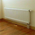
Many building owners in heating-dominated climates are used to the look of fin-tube baseboard. While most don’t relish it as a visual enhancement of the room, they understand its purpose and accept it as a necessary part of the building.
The latest development in low temperature fin-tube baseboard is shown in Figure 2 with a product called Heating Edge that is currently made in the UK, but available in North America.
From the outside it looks very similar to other fin-tube baseboard, but what’s “under the hood” is very different. Heating Edge baseboard has much larger fins than traditional baseboard. The fin area is about three times larger, almost filling the entire space within the enclosure. It also has two ¾-in. copper tubes running through those fins. The tubes can be piped either for parallel flow or in series. In the latter case, the hottest water flows down the upper tube, makes a U-turn at the end and flows back along the lower tube.
Assuming an average water temperature of 110ºF, this baseboard releases about 290 Btu/hr./ft., when the two pipes are configured for parallel flow and the total flow rate through the element is 1 gpm (0.5 gpm through each tube). This increases to about 345 Btu/hr./ft., with a total flow rate of 4 gpm (e.g. 2 gpm per tube). If the two tubes are configured for series flow (hot along top and return along bottom), the output at 1-gpm flow rate drops about 10%.
Consider a 12-ft. by 16-ft. room in a well-insulated home with a maximum heating load of 15 Btu/hr./ft.2 The room’s maximum heating load is thus 2,880 Btu/hr. This could be handled by a 10-ft. length of Heating Edge baseboard operating at an average water temperature of 110ºF and 1-gpm flow rate. To produce equivalent output, a 10-ft. length of conventional residential baseboard would require an average water temperature of about 150ºF. The latter temperature would dramatically lower the efficiency of solar thermal collectors.
|
|
Figure 3. |
Radiant panel solutions
The key to achieving low water temperature operation is using heat emitters with large heated surface areas. The greater the heated surface area, the lower the required water temperature for a given rate of heat output.
By embedding tubing in floors, walls and ceilings, it’s possible to create very large heat surfaces within a room. Radiant floor heating is undoubtedly the best-known form of radiant panel heating. It can be installed in several proven ways that allow it to operate at relatively low water temperatures.
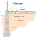
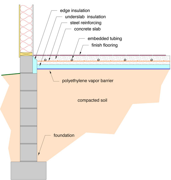
Tubing embedded in a concrete floor slab is the most common form of radiant floor heating. Figure 3 shows a proven construction method.
Notice the tubing has been placed at approximately mid-depth within the slab and the underside and edge of the slab are well-insulated with extruded polystyrene. Both details are imperative in achieving good low temperature performance.
It’s also important to use low resistance (or even no-resistance) floor coverings. A painted, stained or stamped upper surface is ideal. If that doesn’t suit your tastes, consider ceramic tile or vinyl flooring. If you need carpet and still expect reasonable performance, use only ¼-in.-thick commercial-level loop carpet glued directly to the slab. If you ignore this advice and cover a heated slab with ½-in.-thick urethane pad and Berber carpet, all I can say is “better luck next time.”
|
|
Figure 4. |
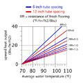
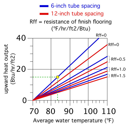
The graph in Figure 4 can guide your tube spacing and floor covering selections. Assuming you are satisfied with 70ºF as the desired indoor temperature, this graph gives you the required average water temperature in the floor tubing based on tube spacing, the R-value of the floor covering (if any) and the rate at which heat must leave the floor (in Btu/hr./ft.2) under maximum heating conditions.
For example, assume the maximum heating load of a room, divided by the area of heated floor in that room was 15 Btu/hr./ft.2 You’ve decided to install the tubing at 6-in. spacing and finish the slab with a sealed stain (Rff=0). The required average water temperature is only about 83ºF. The supply water temperature is typically 8º to 10ºF higher than the average water temperature. Under these assumptions you will only have to supply the slab with 93ºF water under maximum heating load. That’s excellent performance and well within what most solar thermal systems can deliver,
The graph is limited to slabs having a maximum finish flooring resistance of 1.5 and a maximum average water temperature of 110ºF (with the implicit assumption of a maximum supply water temperature of 120ºF). These are the limits I suggest you not exceed if you’re serious about building a good-performing solar combisystem. Here are some other suggested limits for using a heated slab floor supplied by a solar thermal system:
-
Tube spacing within the slab should not exceed 12 in.;
-
The slab should have minimum of R-10 underside and edge insulation; and
-
The tubing should be placed at approximately half the slab depth below the surface as shown in Figure 3. Doing so decreases the required water temperature required for a given rate of heat output. Leaving the tubing at the bottom of the slab will seriously lower performance in systems relying on solar thermal collectors.
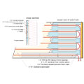
Figure 5
Heated walls and ceilings
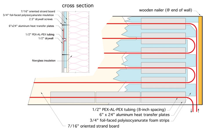
Radiant panels also can be integrated into walls and ceilings. Several of these configurations can operate at the lower water temperatures required by solar thermal collectors. One example is a radiant wall panel constructed as shown in Figure 5.
When finished, this “radiant wall” is indistinguishable from a standard interior wall. Its low thermal mass allows it to quickly respond to changing internal load conditions or zone setback schedules. This latter characteristic is especially important in homes with low heat loss and/or significant internal heat gain from sunlight, people or appliances.
The rate of heat emission from the panel shown in Figure 5 is approximately 0.8 Btu/hr./ft.2 for each degree (F) the average water temperature in the tubing exceeds room air temperature. Thus, if the wall operates with an average water temperature of 110ºF in a room with 70ºF air temperature, each sq. ft. of wall would release about 0.8 x (110 - 70) = 32 Btu/hr./ft2. This is good performance and well within what most solar thermal systems can deliver.
If you plan to install this system on the inside of an exterior wall, make sure the R-value of that wall is 50% higher than non-heated exterior walls. That keeps the rate of heat loss to the outside about the same as for a non-heated wall. If you’re installing this on an inside partition, use a nominal 4-in. fiberglass batt in the stud cavities behind the heated wall. Finally, these walls are best constructed to heights of about 4 ft. above floor. That keeps the radiant heat output in the occupied zone of the room for best comfort.
Another possibility is a radiant ceiling using the same construction as the radiant wall. The only difference is the materials are fastened to the ceiling framing rather than the studs. When installing on a ceiling, the radiant panel construction shown in Figure 5 produces approximately 0.71 Btu/hr./ft.2 for each degree (F) the average water temperature in the tubing exceeds room air temperature.
|
|
Figure 6 |
Panel rads
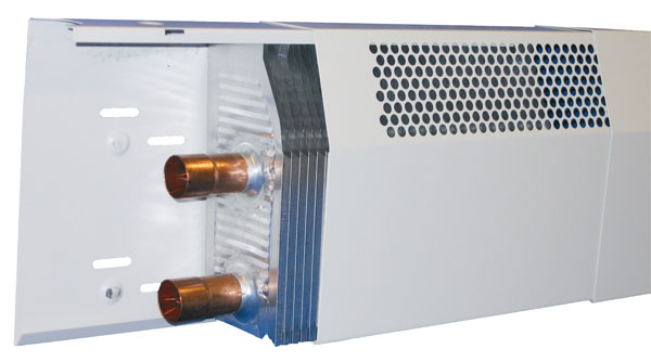
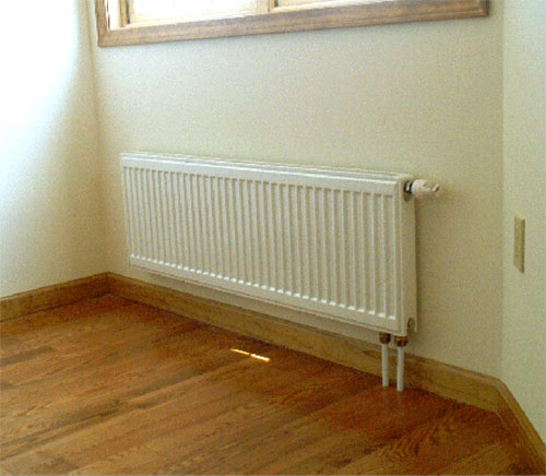
Generously sized panel radiators also can provide good low-temperature performance. Again, the suggested guideline is to size panels so they can deliver maximum required heating output using a supply water temperature no higher than 120ºF. An example of a panel radiator with integral thermostatic radiator valve is shown in Figure 6.
Manufacturers provide output ratings for their panel radiators in either tabular or graphical form. In most cases the listed output is for relatively high water temperatures such as 180ºF. Correction factors are then given, which when multiplied by the listed heat output, give the actual heat output for specific average water temperature and room air temperatures.
As an approximation, a panel radiator operating with an average water temperature of 110ºF in a room maintained at 68ºF provides approximately 27% of the heat output it yields at an average water temperature of 180ºF. Larger panels (longer, taller and deeper) are available to increase surface area to compensate for lower operating temperatures.
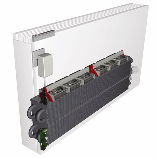
Fan-assisted
|
|
Figure 7 |
If you want the latest in contemporary looks combined with excellent performance, consider the “Low H20” panels from JAGA North America. One product from this line is shown in Figure 7.
A Low H2O panel has a large internal convector element consisting of multiple passes of copper tubing and aluminum fins. This element is housed in a simple powder-coated steel enclosure that serves to enhance convective air movement and provide a low temperature radiant panel surface facing the room. A unique feature of these panels is the rack of “microfans” seen at the top of the convective element. These fans operate on low voltage and only require about 1.5 watts each of input power when operating at full speed. Their primary function is to enhance convective heat transfer when the panel is operating at low water temperatures. They do this very well, boosting low water temperature heat output about 250% compared to the same panel without the fans.
Although some electrical input power is required, it is very small in comparison to common fan convectors with AC-powered C-frame motors. The microfans also are very quiet and can modulate their speed as needed based on the water temperature supplied to the panel. Each panel also can be equipped with a wireless thermostatic radiator valve, which serves to regulate water flow through the panel in response to room air temperature.
Low-temperature heat emitters are only part of a “solar-ready”hydronic distribution system. In the next Solar Thermal Notebook, we’ll discuss piping designs and circulators that work in concert with such heat emitters to maximize system performance. Stay tuned.


