Rules of thumb like this are a good for conceptualizing a design provided the person using them knows all the assumptions they're based on. In this case equating 10,000 Btu/hr with each gpm of flow is based on an assumed temperature drop of 20KF between the supply and return piping to the load. If the system is not going to operate at a 20KF temperature drop, or if the system will use a fluid other than water, Formula 1 can be used to determine the flow rate necessary to convey heat to a load at a specified rate:
Formula 1
f = Q ÷ (k x (Tsupply - Treturn))
Where:
f = required water flow rate (in gpm)
Q = heat transport rate (in Btu/hr)
Tsupply = temperature of supply water (in degrees F.)
Treturn = temperature of return water (in degrees F.)
k = a constant based on the fluid and temperature range. The value of k can be found using Formula 2:
Formula 2
k = 8.02 x d x c
Where:
d = density of fluid at average system temperature (in lb/ft3)
c = specific heat of fluid at average system temperature (in Btu/lb/degrees F)
Here are the values for k for common hydronic fluids at different temperatures:
Water k=495 at 10 degrees F, k=490 at 140 degrees F, k= 487 at 170 degrees F 30% propylene glycol k=478 at 100 degrees F, k=478 at 140 degees F, k=479 at 170 degrees F 50% propylene glycol k=449, k=451 at 140 degrees F, k=453 at 170 degrees F
Let's apply Formula 1 to a conventional hydronic distribution circuit supplying 200,000 Btu/hr to the manifold station of a large floor heating system. Assume the supply water temperature to the floor circuits at design conditions is 110K F with a temperature drop between the supply and return manifolds of 15K F. The supply water temperature is created by blending hot boiler water with cooler return water at a mixing device in the mechanical room. The flow rate needed to transport 200,000 Btu/hr out to the manifold station is shown in Formula 3:
Formula 3
f = Q ÷ (495 x (Tsupply - Treturn)) =
f = Q ÷ (495 x (110 - 95)) = 26.9 gpm
This flow rate will require 2-inch piping between the mechanical room and manifold station if the flow velocity is to be kept under 4 feet per second (fps). Such an example is typical of many commercial radiant floor heating systems where mixing takes place in the mechanical room, and the blended water is then pumped out to the manifold stations.
But what if the mixing were done at the manifold station(s) rather than in the mechanical room? What if high temperature water at say 180K F were to be transported directly to the manifold station(s) before being mixed with cooler return water? The temperature difference between the fluid leaving and returning to the mechanical room would now be 180 - 95 = 85K F. That's more than five times the temperature difference of the previous example. Formula 1 can again be used to see how this effects the flow rate:
f = 200,000 ÷ (490 x (180 - 95)) = 4.8 gpm
The flow rate has dropped to less than 18% that required by the first example. Such a flow could easily be handled by a 3/4-inch pipe. This tradeoff between flow rate and temperature difference has some profound implications for the system that can lower cost and improve control if recognized and utilized.
Minitube Distribution Systems
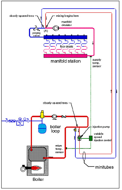
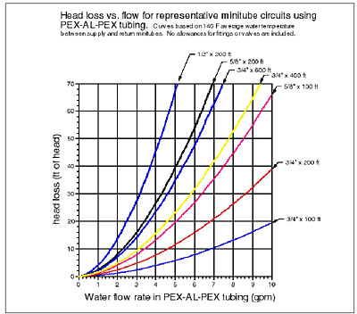
Figure 1 shows a piping schematic for a radiant floor heating system designed to "exploit" the large temperature difference available between hot boiler water and the relatively cool water returning from a slab-type radiant floor heating system. Hot water from the boiler loop is pulled into the supply minitube at a flow rate dependent on the speed of the injection pump. This pump is a typical wet rotor hydronic circulator. Its speed is controlled by one of several available variable speed injection mixing controls. The hot water is transported to the manifold station through the insulated supply minitube and injected into the tee marked (A). Here it mixes with a portion of the cooler water returning from the floor circuits. The mixed stream flows into the supply manifold and out to the floor circuits. The faster the injection pump runs, the greater the proportion of hot boiler water entering the mix point, and the warmer the water supplied to the floor circuits becomes. Heat output from the floor can thus be regulated from zero to full design load by adjusting the speed of the injection circulator.Notice how the supply and return minitubes are coupled to both the boiler loop and manifold loop using closely spaced tees. These creates a primary/secondary interface that prevents the pressure distribution in one loop from interfering with that in the others. From the standpoint of selecting the injection pump, the minitubes can be treated as if they constitute an isolated series circuit. The pump curve for candidate circulators can be compared to the head loss curve of the minitube circuit. The operating point should be at or slightly above the design injection flow rate determined using Formula 1. The graph in Figure 2 shows some head loss curves for representative minitube circuits made of
PEX-AL-PEX tubing.
Multiple Zone Minitube Systems
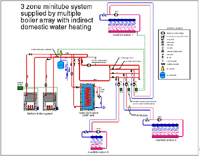
When laying out a floor heating system for a commercial building it's often necessary to locate several manifold stations at considerable distances from the mechanical room. These "satellite" manifold projects are perfect for a multiple zone minitube system. Each manifold station is paired with its own variable speed injection pump system. A piping schematic for a three zone minitube system using a multiple boiler array and indirect domestic water heater is shown in Figure 3.
The primary piping loop has been split into three parallel legs where the minitube circuits are attached. This allows the same water temperature to be available to each injection pump. It also requires a balancing valve in each parallel leg to balance the flows in proportion to the load each minitube zone requires.
Some Necessary Details
The schematics in Figures 1 and 3 show the injection risers run downward from the boiler loop, even if they eventually turn and go up again. Dropping the injection risers at least a couple of feet below the boiler loop piping creates a thermal trap that all but eliminates gravity flow within an inactive minitube zone. Flow-check valves should not be used as a substitute for this trap since they can cause erratic operation of the injection pump at low loads.
Another important detail shown in Figures 1 and 3 is the boiler return temperature sensor. Each variable speed injection control has one. It's there to prevent a cold high mass slab from pulling the water temperature in the system well below the dewpoint of the boiler exhaust gases as the slab slowly warms up. When an injection control senses boiler return temperature below approximately 130KF it slows down or stops its injection pump to prevent heat from being injected into the distribution system faster than the boiler(s) can replace it. Without boiler return protection, this transient situation will cause sustained flue gas condensation in the boiler(s), leading to accelerated fire side corrosion. Such protection should be provided whenever a conventional boiler is paired with a high thermal mass distribution system (minitube system or otherwise).
Minitube Benefits
In addition to reducing the size and cost of distribution piping minitube systems have other benefits:
- If desired, each manifold station can be operated at a different setpoint temperature or outdoor reset schedule. This flexibility is very useful if the zones have different floor coverings or widely varying load characteristics.
- Minitube systems allow the distribution circulator at each manifold station to operate continuously during the heating season, even during periods of zero heat input. Continuous floor circuit circulation is particularly nice in garage types buildings because it redistributes heat from interior slab areas out to areas adjacent to overhead doors. In non-continuous flow systems not protected by antifreeze, floor areas near large overhead doors are prone to freezing when flow through the floor circuits is turned off for several hours (such as during a setback period). Continuous flow past the supply temperature sensor at the manifold station also stabilizes the control loop.
- Minitube systems inherently improve the range of variable speed injection mixing systems. This results from the fact that when AC wet-rotor circulators are used as variable speed injection pumps in systems with short injection risers, they're often capable of delivering design injection flow rates at a small fraction of their full operating speed. In conventional injection mixing systems this requires the installation of a globe valve in the return injection riser to throttle away a substantial portion of the pump's head, thus forcing it to operate at higher speeds near design load conditions. By contrast, the head loss of the longer minitube piping can provide most or all of this throttling effect, and transport water to and from the manifold station in the process.
- In some minitube systems, it may be possible to reduce the size of the manifold circulator since it isn't responsible for flow between the manifold station and the mechanical room. This task is now handled by the variable speed injection pump.
Piping Heat Loss
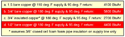
Since the supply minitube carries relatively hot water it's prudent to verify how much heat will be lost as the water makes its way from the mechanical room to the manifold station. I've compared the heat loss of several distribution pipes making a 200-foot round trip circuit between the boiler room and a manifold station, assuming all pipes are surrounded by 70KF air. Table 1 lists the total heat loss for several piping options under design flow conditions.Notice that the heat loss of 1/2 inch tubing carrying 180KF supply water is about the same as that of 1-1/2 inch pipe carrying 110KF supply water. Under the conditions assumed, PEX and PEX-AL-PEX tubing will have about the same heat loss as bare copper tubing of the same size.
These losses are small in the context of transporting 100,000 to 200,000 Btu/hr to a manifold station. Still, the idea is to minimize heat loss from the supply minitube. Therefore the (hot) supply minitube should always be insulated.
Field Experience and Summary
Minitube distribution systems have been successfully used on several projects to date. Two such projects were municipal garages in upstate New York. Another was a marina building in Connecticut. The largest system that I'm aware of so far is a lumber processing facility in Northern Alberta Canada that's approximately 100,000 square feet in size and uses seven minitube zones. Piping costs in the latter project were reduced over $11,000 by using a minitube distribution system rather than the originally planned perimeter piping loop. The largest pump in the distribution system is a 1/6 hp wet rotor circulator.Minitube distribution systems demonstrate how flow rate can be traded off against temperature drop to reduce installation cost and provide a more versatile system in the process. The approach lends itself to many systems (both residential and commercial) where low temperature manifold stations need to be located at substantial distances from the mechanical room. Keep it in mind when your next big radiant system comes along.
