Issue: 8/05
Editor's Note: "Back to Basics"
What's Happening?
Vaporous cavitation occurs as water entering the eye of a circulator's impeller flashes into vapor. You could say that the water "boils"Implosive Results
Cavitation begins when the water entering the eye of the impeller flashes into millions of tiny vapor pockets. The density of this vapor is about 1,500 less than that of liquid water. In other words, the water molecules take up about 1,500 times more space as vapor compared to liquid. This is comparable to a single kernel of popcorn expanding to the size of a baseball.
What happens next is arguably the most interesting but also the most destructive aspect of vaporous cavitation. As the mixture of liquid and vapor flows outward between the impeller disks, its pressure increases because of the head energy it is gaining. When the mixture reaches its vapor pressure, the vapor pockets instantly collapse like tiny punctured balloons. This is what causes the "crackling"

Don't Aid the Enemy
Unfortunately, some hydronic systems are designed, installed, or operated such that cavitation is unknowingly encouraged.Any design or installation detail that creates a drop in pressure near the inlet of a circulator is a potential cause of vaporous cavitation. If such details can collectively pull the water pressure down below its vapor pressure, cavitation instantly occurs. The lower the pressure at the eye of the impeller, the more severe the symptoms.
The following design/installation/operating details should be followed to avoid cavitation:
- Don't locate the circulator upstream (pumping toward) the expansion tank. The differential pressure created by a circulator pumping toward the expansion tank is subtracted from the static water pressure at the circulator's inlet. If the resulting pressure drops to or below the vapor pressure, cavitation will occur.
- Don't put throttling valves, flow-checks, or other components with high flow resistance near the circulator's inlet. Anything that creates significant turbulence or pressure drop at the circulator's inlet should be avoided. As a rule, install at least 12 pipe-diameters of straight pipe upstream of all in-line circulators.
- Don't operate the system at low water pressure. The lower the static pressure at the circulator inlet, the smaller the pressure drop required to initiate cavitation.
- Don't design for high water temperature operation. The higher the water temperature, the higher the system pressure must be to suppress cavitation. You may even come across a circulator that operates quietly when cool, then starts crackling away when the system reaches a higher temperature.
- Do install a good air separator. Dissolved gases in water can create "gaseous"
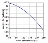 Figure 3. Density of water versus its temperature.
Predicting Cavitation
Over the years, engineers have established a standardized method of predicting when a pump will cavitate within a given piping system. This method is based on a quantity called Net Positive Suction Head (NPSH). It combines the effect of fluid density, pressure and flow velocity relative to the formation of vaporous cavitation.Since the piping through which a fluid travels affects its temperature, pressure and velocity, the value of NPSH will be different at different locations in the system. When trying to avoid cavitation, the location of interest is usually the circulator's inlet port. To be specific, we can say that a given piping configuration and its operating conditions make a certain NPSH Available (NPSHA) to the circulator at its inlet.
Part of the head energy a fluid possesses as it enters a circulator depends on its pressure. If a pressure gauge were mounted near the circulator's inlet, its reading could be converted to a head value by multiplying psi by 144 and dividing by the fluid's density (in lb/cubic-foot).
The same fluid also contains head energy due to its velocity. The faster the flow moves, the more "velocity head" Table 1Equation 1
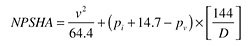 Equation 1
Where:
v = velocity of the fluid entering circulator (ft/sec)
pi = pressure at circulator inlet (psi gauge)
pv = absolute vapor pressure of fluid entering circulator (psia)
D = density of the fluid entering the circulator, (lb/cu.-ft.) (see Figure 3)
NPSHA could be described as the total head of the fluid above the head value at which cavitation would occur; hence, the word net. Like any value for head, NPSH is expressed in feet.
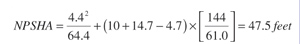 Equation 1 with figures filled in.
Here's an Example
Assume water enters a circulator through a 1-inch copper tube at a flow rate of 12 gallons per minute. The water's temperature is 160The Bottom Line
To avoid cavitation, make sure the NPSHA provided by the piping system and its operating conditions is greater than the NPSHR of the circulator. The greater the NPSHA is relative to the NPSHR, the greater the safety margin against cavitation. When making the comparison, use the NPSHR value at approximately the same flow rate at which the circulator will operate.Cavitation, like corrosion, is best avoided through good design rather than corrected when it suddenly appears. Use the design concepts we've discussed and the mathematical checks to keep the circulators in your systems cavitation free. Then, relish in the virtually silent conveyance of comfort only hydronic systems can provide.
PME Congratulates John Siegenthaler for 2005 APEX Award!
PME would like to congratulate John Siegenthaler for winning a 2005 APEX Award of Excellence for technical writing for his article, "Hydronic Fundamentals, Part 1,"
