
Given the current upward trend and volatility of fossil fuel pricing, there’s renewed interest in heating using wood pellets. Federal incentives that currently cover 26% of some qualified equipment adds enticement toward purchasing pellet-burning stoves.
Pellet-fueled boilers are also available, and we’ve discussed proper piping and control concepts in several past columns. But this month, I want to shift focus to the vent connection between the pellet boiler and its chimney.
Blow back
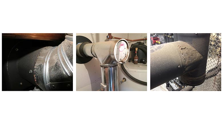
Take a look at the vent connector piping shown in Figures 1a, 1b and 1c. These photos were all taken at pellet boiler installations. Do you see something in common?
Modern pellet-fueled boilers are sophisticated machines. Most of them have an internal draft-inducing blower, the speed of which is regulated based on the oxygen content of the flue gases. This allows the boiler to adjust the excess air supplied to the combustion chamber in an attempt to maintain optimal combustion efficiency.
Properly configured pellet boiler systems incorporate thermal storage, and should only require the boiler to fire 2 to 3 times on a typical winter day. This implies that there will be several hours when no flue gases are passing up the chimney. The chimney will obviously cool off during such times.
When a modern pellet-fueled boiler is combined with a “cold” chimney, the flue gas flow created by the boiler’s inducer blower at startup can be higher than the initial drafting ability of the chimney. The result is slight positive pressure in the vent connector piping. The flue gases and any small amount of fly ash present in that gas will find any exit point in the vent connector piping. That’s why you see the ash accumulating on the outside of the vent connector joints in Figure 1.
Ash accumulation is especially noticeable on standard draft regulators, which have no means of sealing against positive pressure inside the vent piping. This condition is exasperated when the boiler is connected to an exterior masonry chimney, which has high thermal mass and therefore takes quite a while to establish a good draft following several hours with no warm gases passing through.
Dealing with it
Several details can improve or eliminate the ejection of flue gases and ash from pellets boiler venting systems.
First, whenever possible, use a UL-103HT-rated stainless steel prefabricated chimney and route it up through as much heated space as possible on its way to the roof. These chimneys have a small fraction of the thermal mass of a masonry chimney. The inner liner of this type of chimney can warm quickly and thus establish draft quickly when starting from a “cold” condition. When routed up through conditioned space, these chimneys have a “head start” in establishing proper draft temperatures.
If an existing masonry chimney must be used, install a stainless steel liner, and insulate between the liner and existing chimney flue with approved materials — and in conformance with local codes. The idea is the same as with the prefabricated chimney — minimal thermal mass that can warm quickly.
Second, all vent connectors should be made of welded seam or seamless single-wall or double-wall pipe, examples of which are shown in Figure 2.
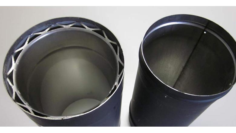
Don’t use galvanized “snap-lock seam” pipe. Remember that positive pressure within the pipe will find any and all paths to the outside. That snap-lock seam in not a sealed connection.
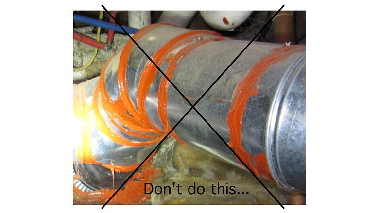
Third, use a high-temperature sealant on all joints, and apply it correctly. Don’t smear RTV silicon on the outside of the joints — as shown in Figure 3. This looks amateurish, and in many cases, the RTV eventually loses contact with the piping and the seal will be lost. This is especially likely on galvanized vent connector piping.
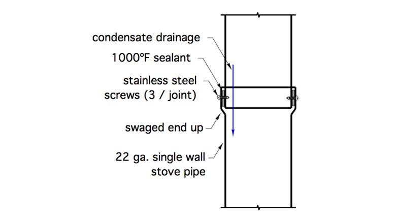
Sealants such as Mill-Pac Black are used to seal components on wood stoves, and are rated to withstand temperatures just over 1,000° F, which is much higher than should normally occur in vent connector piping from a pellet boiler. Place the sealant inside the swaged joint of the pipe as shown in Figure 4. Be sure the swaged end of the pipe faces upward. This keeps any temporary flue gas condensation inside the venting system. When single-wall pipe is used, be sure to use stainless steel fasteners at all joints. Figure 4 shows these details.
On the wish list
One final detail that our European counterparts commonly use is a draft regulator that can seal against positive pressure inside the vent connector piping. Two examples of such regulators are shown in Figure 5.
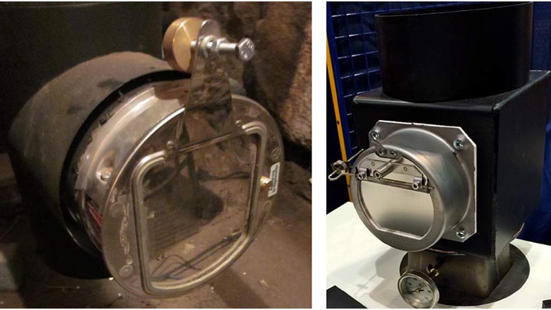
When positive pressure occurs inside the vent piping the pivoting plate in these regulators is pressed against a gasket. The greater the internal pressure the better the seal. These regulators are constructed of stainless steel and have adjustable counterbalance weights to control the negative pressure at which the plate pivots. In my opinion, these are well-engineered and carefully manufactured products.
Unfortunately, these regulators don’t currently have a UL rating. Given our government’s ambitious press to eliminate combustion-based heating, I don’t think chances are good of getting European manufacturers to jump through the “hoops” and cost to get that UL rating. I hope I’m wrong about this.
Drop leg
Another detail that I originally saw in some European design manuals is to place the draft regulator slightly lower than the sloping vent connector pipe, as shown in Figure 6.
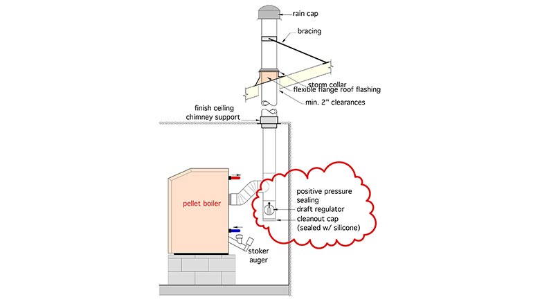
Placing the draft regulator in this manner keeps it below the flue gas stream, and thus cooler. A removable cap seals the bottom of the tee into which the regulator is mounted. The cap provides a catch basin for a small amount of fly ash. It can be easily removed once each season to dump the ash.
The details just presented for a pellet-fueled boiler can also be used with cordwood gasification boilers. Use them to keep the “dust” off that vent connector piping.


