
In larger domestic hot water applications, we often see centralized water heating lineups with or without storage tank equipment to produce and distribute domestic hot water inside buildings and facilities. I often see these more robust systems in healthcare projects, numerous hospitality (hotel) projects as well as some multifamily installations when energy metering is not required for hot water serving the units (apartments). During the design phase, I take a keen interest in analyzing the approach to domestic hot water delivery, the equipment involved, the methods for hot water return and how these systems are represented in design for the specific project. I’m looking for system specifics shown in plan view layouts and system details or schematics that provide all pipe sizing and system configuration for a complete and proper installation.
Too often there are notes with keynotes like “install in accordance with the manufacturer's guidelines.” This is a good reference point to include in the final design deliverable for installation, although, in many instances, I find that we actually are installing basis-of-design (BOD) equipment and design details don’t align with the manufacturer’s details. More diligence is warranted. Providing the proper design details using the BOD manufacturer’s information better prepares the installer and helps avoid systems that do not perform properly under peak load conditions.
Engineering for sizing domestic hot water lineups is another aspect of these installations and a separate topic — system sizing and capacity are rarely an issue. The focus in part here is establishing good alignment between design details and the plumbing contractor requirements, expectations of deliverables and some tips and techniques that should be part of the overall system installation. Time is valuable, so anything we can do in the early (design or preconstruction) phase of our projects avoids RFIs and rework later.
Let’s get into some of the installation and piping techniques that can limit hot water production in large central hot water systems. When these facility problems arise, it can be well after construction is complete and a hotel is full of guests — not exactly the best situation for remedial work!
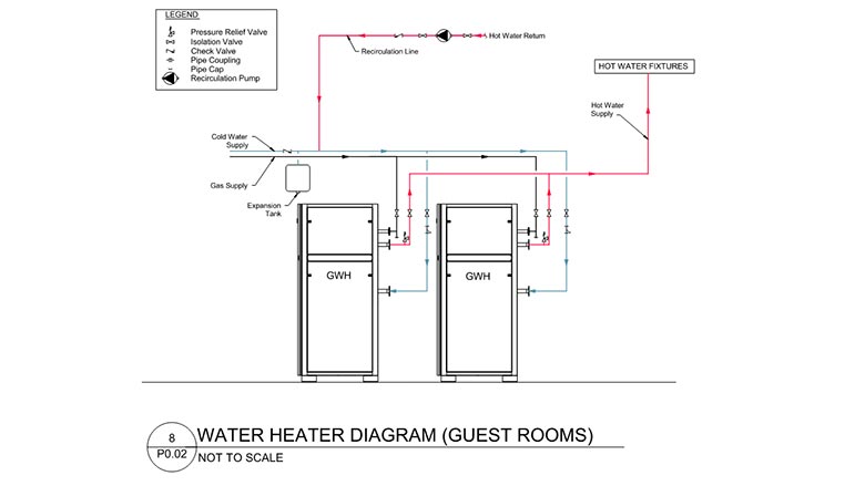
Many of these larger systems utilize natural gas as a fuel source. Here's an example of a partial water heater lineup detail for a hotel project issued in a 100% CD package.
 Click image to enlarge
This pair of heaters are scheduled as tankless instantaneous heaters installed in a larger lineup (shown below). In this piping schematic, the cold water, hot water and natural gas are shown along with several piping accessories required to meet the code and service the equipment. These are condensing appliances, so there will be some condensate and acid neutralization kits to install. Adding the specific equipment tags (there are multiple pairs), gas size connections (from the BOD cut sheet) and the sizes of cold water and hot water mains for equipment connections will set this up for a cleaner takeoff and installation.
 Click image to enlarge
In plan view, there is additional sizing and layout information in the 100% CD package. It’s recommended that full-size tees (not reducing tees) are used when flow adds into the system from the next piece of equipment in the lineup so the full volume of the fitting is available at peak demand. You will notice a single pressure regulating valve (PRV) on the natural gas main. This will work, but it is a single point of failure in the system. Installing smaller, individual gas PRVs at each appliance is typically not a significant cost impact and provides resiliency in the system operation.
When installing a PRV serving gas-fired heating equipment (boilers or water heaters), particular attention must be given to the placement or position of the valve in the line. Typically, the gas PRV must be installed a certain number of pipe diameters (perhaps 10 or more) upstream of the appliance or there may be a specific distance requirement (2 feet or 5 feet). Setting the PRV back from the appliance offers pipe volume and a more stable gas supply as firing rates change. Refer to the manufacturer’s installation instructions for the PRV installation location. With respect to gas pressure and piping capacity, the lower-pressure downstream piping from the PRV often requires a larger pipe size to be able to carry the same volume of gas as the higher-pressure line. Refer to the gas pipe sizing charts included in the installation manual or the Fuel Gas Code tables for the capacity, pipe sizes and pipe lengths based on final field conditions. There’s a lot more equipment being installed in this equipment space in this project example, our engineering team will definitely be spearheading a pre-install meeting and watching the system model as it's developed for this area.
Water distribution piping materials that connect the equipment components and distribute domestic water inside the building can vary. CPVC, copper and stainless steel piping are all permissible along with various joining methods such as solvent weld, brazed, soldered and grooved. When plastic systems are being installed that use primer and glue to set the joint, keep in mind that these joints have a cure time before pressure can be applied to the line. This should be considered for future service, repairs or component replacement work as it applies to material selection(s) to avoid extended downtime for a system that serves an entire building or facility. It's a good idea to review the system layout and consider the addition of extra valves on main headers or in strategic locations to better facilitate individual component replacement or system repairs. Some of our plumbing trade partners are installing copper across the water heating equipment line and then converting to CPVC for building distribution once the mains leave the equipment room.
With respect to gas pressure and piping capacity, the lower-pressure downstream piping from the PRV often requires a larger pipe size to be able to carry the same volume of gas as the higher-pressure line.
Pressure boosters are common in mid-rise and high-rise buildings. There are multiple arrangements for producing domestic hot water and delivering it to the upper zones in a building. Locating the hot water plant at the top of the building can help alleviate problems associated with hot water return pressures as opposed to when the equipment is in the basement or lower level of the structure. When the municipal water supply pressure can support the lower levels of the building supply, the domestic water heater lineup would not have to see elevated pressures prior to being pumped to the upper floors.
When boosted water pressure is placed on the water heating equipment, factory-standard safety relief valves likely need to be replaced to provide proper operation of the system. Take the time to review the system configuration and these details with your equipment vendor. Hot water return on boosted pressure systems can get tricky and should be reviewed prior to construction. Equal water pressure balance across the hot and cold water supply distribution is important for the proper operation of fixtures. The water pressures entering the master mixing valve(s) need to be balanced for proper mixing and temperature delivery to the building. Periodic field QCQA inspections during construction to check that the installation matches the design layout will help avoid rework. I discovered one mixing valve installation where boosted cold water supplied the valve and hot water at municipal pressure served the valve. The design provided for initial mixing, then CW/HW booster pump service to the building. Fortunately, we caught this prior to final piping and insulation work. Field conditions and constraints can sometimes unknowingly affect pending system operation.
In closing, these larger systems often have networking capability which can help facility teams better operate and manage domestic hot water service. Alarms can be communicated, and status can be observed remotely without having to physically go into the mechanical room on a regular basis.
Make sure you’re having the conversation with your client or owner about options here and cost to implement a networking option. What lessons or good practices do you have to share on large domestic hot water installations? Please reach out to your industry partners and professionals for any support you may need!


 systems")