
It’s been a while since this column addressed solar thermal applications. The use of solar thermal systems has declined significantly over the last decade as solar electric (e.g., photovoltaic) systems have grown to dominate the solar energy market. Still, viable applications for solar thermal technology remain, as does its potential to contribute to efforts for decarbonization of thermal energy systems.
Chasing rainbows
The return on investment for a solar thermal system is highly dependent on the load it is paired with. The original focus of solar thermal systems — back in the 1970s — was for space heating. Houses were constructed as supporting structures for massive solar collector arrays in an attempt to approach 100% solar heating. Many of those collector arrays were grossly oversized for swing season loads, and required costly heat dump provisions to “survive” intense summer sunshine. A controller failure or power outage during a bright and hot summer afternoon lead to pressure relief valve openings, thermal breakdown of antifreeze solutions and even irreversible material outgassing within the collectors that degraded their subsequent performance.
That first round of interest in active solar thermal technology within the U.S. all but died during the latter 1980s, and remained in that state through much of the 1990s and first part of the 21st century. The solar coals were rekindled around 2008 driven by increasing concerns over global warming as well as some energy price spikes. However, this time around, much of the industry recognized that using solar collectors to offset a high percentage of conventional fuel for space heating wasn’t a good idea.
Domestic water heating became the preferred load to be paired with solar thermal collectors. The primary rationale being that domestic water heating was a year round load. As such, it benefited from abundant solar radiation and higher ambient temperatures for several months every year. Another benefit was that domestic water heating operated as lower average water temperatures compared to those needed for space heating applications.
Sweet spot
One active solar thermal system configuration that has always interested me is what I call a “solar DHW+” system. The primary load for these systems is domestic water heating. The “+” implies a small contribution to space heating, mostly during swing seasons. This approach keeps the collector array limited to minimize overheating potential in summer. It also leverages major components of the system, such as the thermal storage tank, for multiple functions. The energy collection potential of a Solar DHW + system is also better matched with the load in modern energy efficient homes.
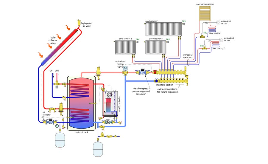
One approach to a solar DHW+ system that uses a dual coil thermal storage tank is shown in Figure 1.

The water in the tank’s shell is “system water,” not domestic water. The lower coil provides heat input from the solar collectors. Its position within the tank maximizes the log mean temperature difference (LMTD) between the outer surface of the coil and the coolest water in the tank. The solar collectors are part of a closed circuit operating with an antifreeze solution. That circuit is equipped with filling/purging valves, a circulator, air separation, expansion tank, pressure relief valve and high point air vent.
The circulator is operated by a differential temperature controller that continually monitors the temperature in the lower portion of the storage tank and the absorber plate in one of the solar collectors. The circulator control action could be on/off or variable speed, depending on the temperature differential. Specialized circulators are available that can modulate the flow rate of the solar collector array to maintain a user set temperature difference between the collector temperature sensor and storage tank temperature sensor. This control action reduces the potential for circulator short cycling under marginal solar conditions.
The upper coil extracts heat from the system water in the tank and transfers it to domestic water. The upper coil must be constructed of copper or stainless steel that’s compatible with domestic water. This is a “single pass” coil. Cold domestic water enters the lower coil connection and absorbs heat as it flows upward and eventually exits the coil. Combination isolation/flushing valves have been installed near the inlet and outlet of this coil, which allow it to be periodically isolated from the system and flushed with a mild acid solution to reduce any scale build-up.
The temperature of the domestic water leaving the upper coil depends on the temperature of the water surrounding the coil, as well as the coil’s surface area and the flow rate through it. Slower flow rates may allow the domestic water leaving the coil to approach the temperature at the top of the tank. Rapid flow rates combined with smaller coils, or coils that have accumulated mineral deposits, will provide less heat and thus lower coil exit temperature. As a guideline, I suggest keeping the water temperature at the top of the tank at least 10° F above the expected DHW outlet temperature. It’s also crucially important to include the ASSE 1017 rated anti-scald mixing valve in the DHW assembly to protect against high water temperatures entering the building’s plumbing distribution piping.
This boiler operates whenever the solar collectors cannot maintain a sufficient temperature at the top of the tank. The mode of operation could last several days during winter in cold and cloudy climates.
The thermal mass of the tank helps stabilize domestic hot water delivery. The tank also provides buffering for the zoned space heating system, which in Figure 1, is controlled by zone valves combined with a variable-speed pressure-regulated circulator. This system configuration is based on the assumption that the heat emitters can handle potentially high water temperature during extended periods of sunny weather. An example of such heat emitters would include panel radiators, fan-coils or fin-tube convectors.
Providing protection
When low temperature emitters such as most radiant panels are used, they needed “protection” from high water temperatures. This can be provided by a mixing valve should be installed upstream of all heat emitters.
Figure 2 shows and alternative distribution system that contains panel radiators as well as some radiant panel circuits. Flow through all distribution circuits is regulated by thermostatic valves, which allow independent comfort control in each room.
A three-way motorized mixing valve has been added to the distribution system. Its primary purpose is to protect the radiant panel circuits against potentially high water temperatures during prolonged sunny weather. The controller for this valve monitors the supply water temperature to the distribution system. When necessary, it mixes hot water from the thermal storage tank with cooler water returning from the distribution system to limit the supply water temperature. This valve and controller could also be used to “smoothen” the supply water temperatures to all heat emitters using outdoor reset control.
Electrifying
Another variation on this system is to use an air-to-water heat pump as the heat source. With this approach, it’s critically important to keep the water temperature in the system as low as possible to maximize the heat pump’s COP. Unfortunately, this works against the need to heat domestic water up to typical delivery temperatures. If the desired DHW supply temperature is 120°, the water at the top of the tank needs to be maintained close to 130°. Although many air-to-water heat pumps can achieve these temperatures, they do so at the expense of significantly lower coefficient of performance (COP).
Based on simulations I’ve done, the seasonal COP of the heat pump improves when the temperature in the buffer tank is maintained using outdoor reset control, along with using electricity for supplemental domestic water heating. This concept is shown in Figure 3.
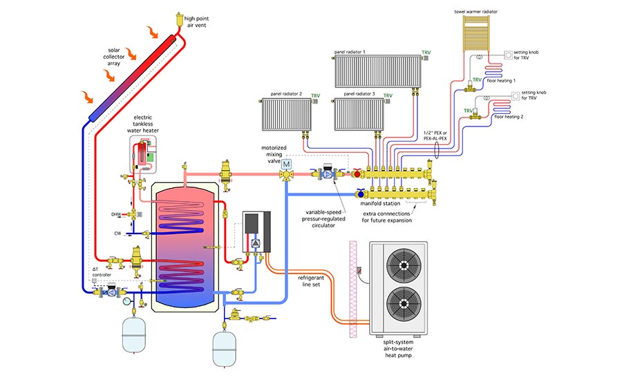
The split-system air-to-water heat pump replaces the boiler. The domestic water is “preheated” as it passes through the upper tank coil. A tankless electric water heater provides the final temperature boost, making this an all-electric system. All domestic hot water passes through the ASSE 1017 anti-scald valve before entering the building’s plumbing distribution system.
Still viable
The “Solar DHW +” concept represents a “sweet spot” for active solar thermal technology that can coordinate well with low-energy houses. The all-electric option shown in Figure 3 is especially well suited for homes aiming for “net zero” energy status. It’s worth keeping this concept in your design portfolio.


