
In the closing days of 2020, the federal government approved one of the largest renewable energy spending bills in over a decade. This time around, it included an uncapped investment tax credit of 26% on “qualified” biomass boilers fueled by cordwood, wood pellets or chips.
The criteria used for establishing “qualified” technology, at the time of this writing, is somewhat non-specific. The qualifying number for efficiency is simple — 75%. Exactly how that efficiency metric is defined is another matter. For example, is it based on the higher heating value (HHV) or lower heating value (LHV) of the fuel? Is it based on a prescribed testing procedure administered by an approved testing laboratory, or solely on information supplied by the boiler manufacturer? The IRS and other federal agencies such as the EPA will ultimately pin down the specifics that determine what equipment can claim the tax credit. My expectation is that the bar will be set high, and that only state-of-the art biomass combustion technology will make the cut. Still, these credits will be a short-term shot in the arm for the biomass boiler industry, putting it on a somewhat equal incentive footing with the solar and geothermal heat pump industries.
One of the fundamental differences in applying biomass boilers compared to standard fossil fuel boilers, is the need for long (multi-hour) combustion cycles to achieve high thermal efficiency and low particulate emissions. In the vast majority of applications, this requires water-based thermal storage, and plenty of it. One guideline for pellet-fueled boilers is a minimum thermal storage volume of 2 gallons per 1,000 Btu/h of peak boiler output rating. For cordwood gasification boilers, which should be operated in “batch” burn cycles, a reasonable guideline is 130 gallons of thermal storage per cubic foot of primary combustion chamber volume. A residential scale cordwood gasification boiler would typically have 5-to-8 cubic feet of primary combustion chamber volume. Thus, the corresponding thermal storage, based on the stated guideline, would be 650 to 1040 gallons of water. How to contain all that water is a major part of designing a good system.
A closed case
My preference for thermal storage has always been a pressure-rated tank. This allows the entire system to be “closed” (e.g., isolated from the atmosphere). When closed tanks over 119 gallons are used in hydronic systems most codes require them to be listed and labelled under the ASME section VIII pressure vessel code. Figure 1 shows and example of an installed 750 gallon pressure-rated thermal storage tank, coved with site-installed insulation.

Although, it’s generally not a problem to source tanks that meet the ASME requirement, they are expensive, and they’re also large and heavy. If you plan to use an ASME listed tank on a project, it’s critical to plan out the logistics of getting it on-site, into the building and to its installed location. It’s also important to plan for the possible (but arguably improbable) contingency of removing or otherwise servicing that tank over what should be many decades of service life.
An open case
The cost and logistical requirements associated with large pressure-rated tanks often lead designers to use non-pressurized thermal storage tanks, especially for systems going into existing buildings. Most of the currently available non-pressured tanks are delivered “knocked down.” Their components are easily moved into basements or other suitable locations, through standard doorways, and then assembled. After assembly, the tank is filled to a specific level with water. A small vent hole in the tank’s insulated lid ensures that the surface of the water is always at atmospheric pressure.
When a non-pressurized thermal storage tank is used with a cordwood gasification boiler, or a pellet boiler, it’s necessary to separate the boiler from the tank water using a heat exchanger. Not doing so would allow dissolved oxygen in the tank water to corrode the steel heat exchanger in the boiler. For the same reason, a closed hydronic distribution system containing steel or iron components needs to be separated from tank water by another heat exchanger.
For several decades the “default” hardware solution for this heat exchange requirement has been to suspend coils of copper tubing within the tank. In some cases, several hundreds of feet of 3/4-inch copper tubing is used. Multiple coils, connected in parallel, is a way to increase heat transfer surface area without creating excessively high pressure drop. Figure 2 shows an example of multiple coil heat exchangers suspended within a thermal storage tank.
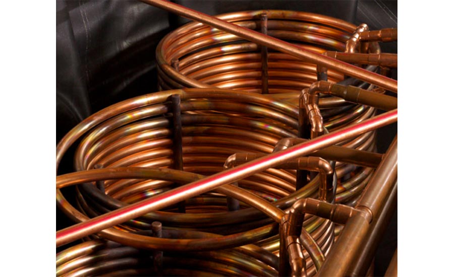
When water is pumped through a coil heat exchanger under normal (turbulent flow) conditions, forced convection occurs between the water and the inner surface of the coil. Natural convection occurs on the outside of the coil. Natural convection is a relatively “weak” effect compared to forced convection (e.g., natural convection coefficients are typically only 10% or less than those associated with forced convection). A 10-to-1 ratio in convection coefficients between the inner and outer surfaces of the coil implies that the outer surface of the coil must be 10 times larger than what would be required if the inner and outer surfaces operated under the same forced convection conditions. This is why immersed coils have to be so large — they are limited by natural convection at the outer surface.
From internal to external
Traditional approaches —such as use of suspended coil heat exchangers in non-pressurized thermal storage tanks — tend to become defaults in designer’s minds. This was understandable when the only alternative were large, heavy and expensive shell and tube heat exchangers. However, modern brazed plate stainless steel heat exchangers present a compelling alternative to immersed coils.
One of the biggest benefits is that forced convection heat transfer occurs on both sides of a brazed plate heat exchanger. This drastically reduces the heat exchange surface area required for a given set of operating conditions.
Another benefit of using external heat exchangers is serviceability. Although, with proper selection, installation and fluid maintenance, there’s not much that can go wrong with a brazed plate heat exchanger. It remains much easier to access than an immersed coil inside a tank.
Brazed plate heat exchangers can also be selected with tight approach temperature differences, which reduces the thermal penalty associated with any heat exchanger (e.g., the necessary log mean temperature difference between the two fluids to enable a specific rate of heat transfer).
The use of a brazed plate heat exchanger does require another circulator to create flow between the heat exchanger and tank water. Since the tank water “communicates” with the atmosphere through a small vent hole in the tank’s lid, that circulator needs a volute made of stainless steel or bronze.
Subtle details
Figure 3 shows one way to use two brazed plate heat exchangers to connect a cordwood gasification boiler, and a closed hydronic distribution system, to a non-pressurized thermal storage tank.
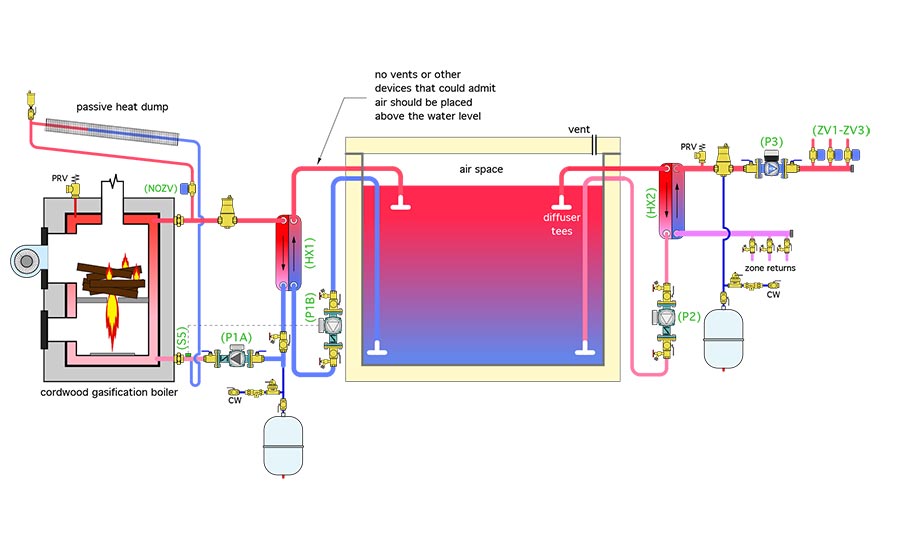
The boiler-to-tank heat exchanger is sized to transfer the boiler’s maximum rate of heat output to the tank water with only 5° F difference between the water entering the heat exchanger from the boiler, and the water leaving it for the tank.
Circulator (P1A) runs at a constant speed whenever the boiler is enabled to operate. The stainless steel circulator (P1B) between heat exchanger (HX1) and tank varies its speed in response to the boiler inlet temperature. At boiler inlet temperatures below 130°, circulator (P1B) is off. Its speed ramps up as boiler inlet temperature climbs above 130°, reaching full speed at an inlet temperature of 140°. This control action prevents the boiler from operating with sustained flue gas condensation.
The pipe carrying hot water from heat exchanger (HX1) passes through the tank wall above the water line, and terminates in a bullhead tee. The latter minimizes mixing and helps preserve beneficial temperature stratification within the tank.
Note that circulator (P1B) is mounted low relative to the water level inside the tank. This increases the net positive suction head available to the circulator and helps prevent cavitation. This is important because the combination of zero gauge pressure at the water surface and potential for relatively hot water in the tank both narrow the preventative margin against cavitation. It’s also important to minimize the head loss in the piping leading to the inlet of circulator (P1B).
Another critical detail is not to install any vent, valve or other device that could allow air into the system within the “gooseneck” piping that's slightly above the water level inside the tank. This portion of the piping is under slight sub-atmospheric pressure. Any device that allows air to enter here would break the water column supplying circulator (P1B).
Finally, a set of “purging flanges” are shown on each side of circulator (P1A). These allow water to be forced into the piping to displace air when the system is commissioned.
The details between the tank and load side heat exchanger are similar to those on the heat input side. A variable-speed pressure-regulated circulator provides flow to the zoned distribution system.
Because there are two completely isolated closed-loop portions within the overall system, two pressure relief valves, two expansion tanks and two make-up water assemblies are required. Those expansion tanks can be relatively small because they only service their respective closed-loop sub-systems. The expansion and contraction of water in the tank simply changes the water level slightly. No expansion tank is needed for this portion of the system.
Next month, I’ll show you how to include an auxiliary boiler in the system, and add controls that ensure that none of the heat from that auxiliary boiler ends up in thermal storage.

