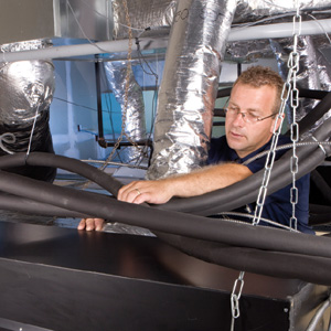
Wellington Mechanical Group’s Alex Hof works on a chilled
beam system. Photo by Andre Van Vugt.
Tracing radiant technology’s genealogy, a new member of the family recently entered our consciousness: chilled beam radiant cooling. With chilled beam systems, chilled water circulates through tubing embedded in a metal ceiling fixture to wick away heat.
What makes this technology so interesting is its broad applicability for commercial structures and extreme energy and thermal efficiency. A key advantage is that a chilled beam system requires very little ceiling space and height, or, in the parlance of commercial architects and designers, it conserves interior real estate.
Another key advantage, functionally and financially, is that water - the main transporter of thermal energy and much denser than air - permits a very high energy- carrying capacity and a smaller transport system: pipes. A forced-air system is, by its very nature, greatly less efficient because of the inherently low density of air and requires large ducts to transport Btu.

Active chilled beams were installed as part of a renovation
to an office tower in Chicago.
Chilly In The Windy City
The structure located at 250 S. Wacker Drive in downtown Chicago is a 15-story, multitenant office tower with retail space on the first floor. The first and top floors had dedicated HVAC systems separate from systems serving the second through 14th floors. These intermediate floors had a floor-mounted induction perimeter system and a constant volume-variable temperature interior system. Each of the floors had about 14,300 square feet of rentable floor area (215,000 square feet total).A major renovation of the building included removal of the building’s exterior walls and glass, and gutting of the structure down to the concrete. Building owners concluded the existing induction units and enclosures would have to be replaced.
Fortunately, the renovation involved a change to 100% low-e exterior glass, which significantly reduced the building’s heating and cooling loads. Heat losses along the perimeter were reduced to less than 200 Btu/lineal foot, which made it possible to provide comfort conditioning of interior spaces with active chilled beams mounted overhead.

250 S. Wacker Drive in downtown Chicago.
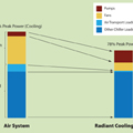
Figure 1.
The Ultimate Integration
Let’s delve into the chilled beam concept a little further. Because chilled beams are ceiling-mounted and do not use drain pans, the chilled water supply temperatures must be above the ambient dew point. As a result, dehumidification, or latent cooling, is handled by a separate 100% dedicated outdoor air system (DOAS) supplying dry, conditioned air to the space.Passive chilled beams employ natural convection, while active chilled beams employ forced convection. Passive chilled beam systems supply the DOAS airflow through a separate diffuser or grille in the room. An active chilled beam supplies the DOAS airflow through the chilled beam, thereby increasing the capacity of the cooling coil through forced convection.
The amount of outside air required to operate a typical chilled beam system is much less than that needed for a forced-air system. A chilled beam system typically needs only one air change per hour, using outside air to pressurize the space to prevent the infiltration of outside air. With a forced-air system, that need grows to eight to 10 air changes of recirculated (and fresh) air to cool a space.
Also reduced is the ceiling space typically required for ductwork. The amount of air circulated by the central system is also dramatically reduced, often 80% to 90% less than with conventional, all-air systems. Of course, this dramatically reduces the horsepower to circulate air within interior spaces.
The net result is lower energy consumption and operating costs. Studies have shown - in typical U.S. commercial buildings - that fan energy is often second only to lighting in energy consumption. With active chilled ceiling and chilled beam systems, energy to operate fans is dramatically reduced due to the relatively small amount and low pressure of the primary air being circulated by the central system.Figure 1shows that a radiant cooling/chilled beam system can reduce electrical energy demand by almost 25%.
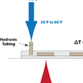
Figure 2.
Beam Me Up
Chilled beams sound futuristic, but many trade professionals are surprised to learn the technology is relatively simple and straightforward.In a radiant chilled ceiling system, 50% to 60% of the heat transfer from a chilled panel is radiant, while 40% to 50% is convective (as shown inFigure 2).
The chilled water temperature must be above dew point to prevent condensation from forming on the underside of the panels. This is typically in the range of 55 to 60 degrees F. The driving force or temperature difference between the chilled water and a room at 75 degrees F is therefore reduced, falling within the range of 15 to 20 degrees F as opposed to a conventional chilled water system using 40 to 45 degrees F chilled water and a range of 30 to 35 degrees F temperature difference.
As a result, higher chilled water flow rates are required to achieve reasonable capacities. These flow rates are in the range of 4.5 to 6 gpm per ton using chilled water delta Ts of 4 to 5 degrees F as opposed to conventional chilled water systems of 2 to 3 gpm per ton using delta Ts of 8 to 12 degrees F as shown in Figure 2. The chilled water flow rate for chilled panels and ceilings is therefore approximately double that of conventional chilled water systems.
Even with higher flow rates, the capacity of radiant chilled panels and ceilings is relatively low - in the range of 2 to 40 Btuh/sq. ft. While this is within the range of cooling loads for interior spaces, it may not be adequate for interior spaces with exterior walls. For the European experience in the 1980s, some cooling was better than none.
The Europeans discovered from their experience that by lowering the chilled panel below the ceiling that the convection cooling component of the individual panels could be increased. This satisfied the increased cooling loads from the increased use of computers seen in the 1990s. There also was a desire to provide higher cooling capacities for exterior zones to provide better overall comfort.
By lowering the panel below the ceiling and making it an open coil, as shown inFigure 3, the capacity of the chilled panel can be increased to 120 to 150 Btuh/sq. ft. The industry has designated this configuration a “passive chilled beam.” It resembles a beam when mounted below the ceiling. It is passive since the convective cooling component is natural convection.
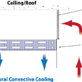
Figure 3.
Passive Vs. Active
Chilled beams are available in three variations: passive, active and integrated/multiservice beams. The difference between passive and active beams focuses on the way airflow and fresh air are brought into the space. Both of these systems are now enjoying significant attention here.Passive chilled beams require ventilation air to be delivered by a separate air-handling system. With active chilled beam systems - sometimes referred to as “induction diffusers” - a building's ventilation air is continuously supplied to chilled beam terminal units by a central air-handling system.
Ventilation air is cooled or heated to partially handle temperature-driven sensible loads, while in the summer it is sufficiently cooled and dehumidified to handle all of the internal moisture-driven latent loads. With active chilled beams, air from the chilled beam is introduced into the space through a slot diffuser, creating a Coanda effect: the tendency of a fluid jet to be attracted to a nearby surface or, in this case, the ceiling.
Inducing warm room air to blow through the chilled coil substantially increases the capacity of the chilled beam. Active chilled beam capacities are in the range of 350 to 600 Btuh/sq. ft. for the coil. Added to this is the capacity of the primary air from the DOAS. Depending on the temperature and quantity of this primary supply air, this can add up to 300 Btuh/sq. ft. of capacity. An active chilled beam can deliver from 500 to 900 Btuh/sq. ft. between the chilled coil and the primary air (see a chilled beam configuration inFigure 4).
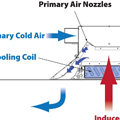
Figure 4.
The technology works in tandem with a central air system, which is calibrated to circulate only the amount of air needed for ventilation and latent load purposes. The chilled beams provide the additional air movement and sensible cooling and/or heating required through the induced room air and secondary water coil.
With an active beam, ventilation air is delivered to the beam by a central air system through ducts. The beam unit itself, then, is not unlike an induction unit turned upside down, mounted to the ceiling. Ventilation air moves through ductwork, forcing room air to make contact with the cooling coil. This air then mixes with the primary ventilation air and delivers it through linear diffusers.
Linear slot diffusers have been used for a number of years in variable air volume systems. Their primary advantage is that they don’t “dump” cold air at low flow rates, making occupants uncomfortable.
It’s in this way that chilled beams transfer a huge portion of cooling (or heating) loads from the less efficient air distribution system to the greatly more efficient water distribution system.

Chilled beam technology has developed into an alternative to
conventional variable air volume systems.
Northern Exposure
In 2008, Taco constructed a new manufacturing plant and office in Milton, Ontario (outside Toronto). Taco wanted to use the facility to demonstrate the latest advanced hydronic systems that the HVAC industry has to offer. This included new radiant cooling and chilled beam technology as well as conventional fan coils and baseboard heating.The building’s existing space was renovated for this new application and included installing new insulation and double-pane windows, which significantly reduced the heating and cooling loads, the size of the mechanical system and energy costs. Further cost reduction resulted from the chilled beam and chilled ceiling systems.
Active chilled beams were used in the training areas as well as general office areas. Chilled ceilings were used to supplement the chilled beams in the training areas.
The chilled beams and chilled ceilings reduce fan energy by a factor of 10, since the only air circulation required is from a 100% DOAS. This system supplies just enough treated, dehumidified outdoor air to slightly pressurize the building, negating natural infiltration of humid outside air.
The amount of fresh air supplied to the building is controlled by a differential pressure sensor measuring the difference in static pressure between the building and the outside. This sensor and accompanying DDC controller then control the speed of the DOAS unit fan to maintain this slight positive pressure. Fan coils were used at the entrances to overcome the inrush of humid air that overwhelms the slight building positive pressure when a door is opened.
With a better thermal envelope for the building, the chilled beams and chilled ceilings can be used for heating without supplemental heat almost everywhere in the building. Again, the use of fan coils at entrances overcomes the inrush of cold air in the winter when a door is opened. Some baseboard was used in offices that had large windows, which were not reduced in size during the renovation to limit possible drafts.
The use of these different terminal units requires different supply water temperatures throughout the building. This would typically result in four piping systems and eight pipes for high-temperature chilled water (chilled beams), low-temperature chilled water (fan coils, DOAS), high-temperature heating water (baseboard, fan coils, DOAS) and low-temperature heating water (chilled ceilings, chilled beams).
Using Taco’s single-pipe LoFlo system, the piping was reduced to two pipes - one pipe carries low-temperature chilled water and one pipe carries high-temperature heating water. In addition, these pipes are smaller than a conventional system’s pipes. The LoFlo Mixing Block contains an injection pump that mixes up low-temperature chilled water to high temperature where required, and mixes down high-temperature heating water to a lower temperature where required.
As more systems are installed in North America, chilled beam technology has developed into an alternative to conventional variable air volume systems.
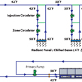
Figure 5.
Injection Mixing Systems
Taco has introduced technology to help radiant cooling/chilled beam systems achieve energy savings.Although radiant cooling and chilled beams reduce fan electrical energy demand and consumption up to 10 times from an all-air HVAC system, the pump energy demand doubles. Now if the pump energy could be reduced, then a radiant cooling/chilled beam system could achieve significant energy savings.
Taco’s new, award-winning LOFlo® injection mixing system accomplishes this. Injection pumping has been used for a number of years in radiant heating systems by mixing down the higher temperature boiler water (at 180 degrees F) to that needed for a radiant floor panel (100 degrees F to 120 degrees F). This same principal can be applied to a radiant cooling system, only in reverse-to mix up low temperature chilled water (40 degrees F to 45 degrees F) to that required by a chilled ceiling panel or beam (55 degrees F to 60 degrees F).
Shown inFigure 5is a schematic piping layout for a radiant cooling/chilled beam, low flow/low temperature injection piping system. In this system, instead of the primary chilled water flow being double that of a conventional chilled water system, it requires only one-quarter of the flow. This is the case since the primary chilled water system temperature difference is now 16 degrees F instead of a radiant cooling/chilled beam system of 4 degrees F and a conventional system of 8 degrees F.
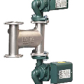
Taco’s new LOFlo® Mixing Block
Taco’s new LOFlo® Mixing Block is a prepackaged unit consisting of a variable speed injection circulator and constant-speed zone circulator. The variable-speed injection circulator is controlled by a sensor that monitors incoming water temperature to a radiant panel (floor, wall or ceiling) or chilled beam (ceiling). The constant-speed zone circulator is controlled by the room thermostat.

