Photos courtesy of Victaulic.
Deflection of pipelines within a structure is often a concern for engineers designing and specifying for pipe installation. If not adequately accommodated, repeated stress on a piping system can cause damage to equipment and threaten the structural integrity of the building itself.
There are also business implications of inadequate accommodation for deflection that result in unsatisfied owners, whose occupants may complain about underperforming systems, noisy pipes, damaged equipment or aesthetic impacts. These issues affect the engineer and contractor’s bottom line, since they may need to perform numerous callbacks in an attempt to fix the problem.
With structures becoming taller, larger and more complex in design, addressing deflection and settlement concerns creates an additional challenge for the engineer. Because the business risk is significant if a system design causes undue stresses on the piping system -forcing rigidly constructed piping/components to bend - it is essential for engineers to understand the system requirements at the design stage to alleviate or accommodate deflection and settlement.
Grooved mechanical piping systems can address forced pipeline deflection or misalignment in a piping system due to settlement and accommodate building sway due to thermal transients and wind loads in vertical risers. They also accommodate linear piping movement from thermal changes and building creep. Most often specified as a fast, safe and reliable alternative to welding, grooved mechanical pipe joining has a history of effectively minimizing deflection risks and accommodating for settlement in a variety of structures.
Grooved Couplings
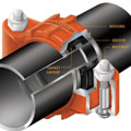
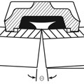
Grooved mechanical couplings are available with two performance features. One class is designed as “rigid” and the other as “flexible.” Rigid, grooved mechanical couplings are designed to “fix” the joint in its installed position, permitting neither linear, angular nor rotational movement at the joints, although it is possible to achieve movement by utilizing grooved expansion joints. On the other hand, flexible grooved mechanical couplings are designed to allow controlled linear and angular movement at each joint, which can accommodate pipeline deflection, building creep and settlement.Grooved mechanical couplings allow for movement in the pipe due to the design of the components. The dimensions of the coupling key are narrower than the groove in the pipe, allowing room for that coupling key to move in the pipe groove while maintaining the pressurized seal of the gasket. Additionally, the width of the coupling housing allows for pipe end separation, therefore leaving room for controlled linear and angular movement. The mechanical coupling remains a self-restrained joint and the pressure-responsive design provides sealing even under deflection and pipe movement.
Grooved mechanical couplings offer an alternative to welded U-shaped expansion loops, welded offsets, expansion joints and rubber bellows. These couplings are easier to install and accommodate deflection and linear movement within the design capability of the coupling, all the while doing this within the product’s “free range of motion.” This means that imparted deflections can be accommodated in smaller spaces with low stress on the components.
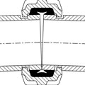
The drawing above shows how
flexible couplings deflect from the straight line to allow for building
settlement.
Accommodating For Settlement
Unanticipated pipeline deflection can damage a building’s equipment or even compromise the structural integrity of the building itself. The piping system designs must work in concert with the building design. Deflection imposed on a piping system may occur due to uneven settlement, particularly when considering new additions to existing structures. A newer structure may settle at a greater rate and flexibility and be designed into piping systems crossing the structures.Piping misalignment due to uneven building settlement is addressed by using an even number of flexible couplings and permitting the intermediate pipe to “toggle” as the movement occurs. To determine the number of couplings required, define the amount of lateral misalignment on a particular pipe run and the length of that pipe run. The objective in designing for misalignment is to achieve the required displacement using the minimum number of couplings. Due to symmetry around a transition point, the point of inflection is a pipe spool and not a coupling.
The number of couplings and the length of the pipe spools are two variables that can be altered to obtain the desired misalignment. Other factors, such as the maximum angle of deflection at each coupling and the maximum pipe end separation, are a function of the size and style of coupling being used.
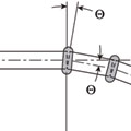
The grooved coupling allows for
controlled angular movement that may result from deflection.
Thermal Transients
Thermal transients may impose deflection on a piping system as the pipe grows when heated and contracts when cooled. All materials, including pipe, machinery, structures and buildings experience dimension changes as a result of changes in temperatures. This will often occur at directional changes, or cause “bowing” at the midpoints of long, straight pipe runs, resulting in stress on the piping system and equipment.Three common methods of accommodating thermal expansion and contraction are:
- Providing an expansion joint;
- Allowing the system to “free-float” and the pipe to move in a
desired direction through the use of anchoring and/or guidance, if necessary
taking into account the capability of branch connection or changes in
direction, which may result in harmful bending moments; and
- Utilizing the linear movement and deflection capabilities of flexible grooved couplings.
Flexible grooved couplings provide deflection capabilities to accommodate pipe movement in long, straight runs or for use in expansion loops, and they allow angular flexibility and rotational movement to take place at joints. To provide for these thermal changes, sufficient flexible joints must be available to accommodate for the anticipated movement. In order to determine the appropriate number of couplings to use, compute the change in the linear length of the piping system by taking into account the length and size of the piping system and maximum and minimum operating temperatures.
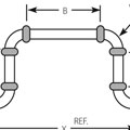
Figure A: Expansion Loop
As system temperatures lower and the pipe run contracts, the loop expands and the deflection capability of couplings accommodates this movement (Figure B). As system temperatures increase, the opposite effect occurs as the pipe run expands and the loop contracts, with the couplings accommodating the deflection in the opposite direction (Figure C). A significant benefit to using this configuration is that a loop constructed in this manner will be a half to a third of the size of a welded loop with the same capacity and will accommodate the movement without inducing stress into the pipe.
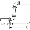
Figure B: Thermal Contraction - Pipeline Shrinks - Loop Expands
Building Creep Or Subsidence
Similar to thermal transients, deflection or linear movement imposed on a piping system may occur due to building creep, which is the common term for the amount of actual building shrinkage that will occur over time. This is an important consideration for high-rise construction.Accommodating building creep can be addressed three different ways using mechanical piping systems: flexible system, rigid system or a combination of both.
In a flexible grooved system utilizing only flexible grooved mechanical pipe joints, risers are installed with anchors at the top and bottom with the piping guided every other pipe length to prevent “snaking” of the line. A sufficient number of flexible couplings must be utilized to accommodate the anticipated movement. Pipe gapping of the pipe ends within the coupling is required in order to allow the riser to compress with the building.
In a rigid system utilizing only rigid grooved mechanical pipe joints, risers can be treated similar to a welded system; where movement is required, expansion joints or offsets are designed into the riser to accommodate movement and prevent damage to components.
By designing risers with a combination of both rigid and flexible grooved joints, engineers can utilize rigid couplings to reduce guiding requirements and the flexible grooved joints to accommodate the movement required.
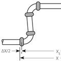
Figure C: Thermal Expansion - Pipeline Grows into Loop - Loop Contracts
Sway in Tall Buildings
Vertical riser piping in tall buildings is often subject to deflection due to heavy wind loads, which cause the building to sway. Where the pipe is rigidly fixed to the building structure, freedom of motion must be designed into the piping to permit it to move in unison with the building. Flexible couplings have been used on vertical risers to provide the necessary freedom of motion so that the pipe sways harmlessly with the building.Grooved mechanical couplings offer an alternative to welded expansion loops, welded offsets, expansion joints and rubber bellows because they provide rigid or flexible joints, which gives the system designer a variety of options for managing piping movement and providing an optimal system design.
On a recent high-rise project in Chicago, the engineer was able to accommodate the piping movement caused by building creep and thermal transients through the deflection characteristic of flexible couplings.
Taking into account the maximum Delta T (change in temperature) that the piping would experience and the building creep, the engineer calculated the amount of movement that would occur within a given run of piping. Based on these calculations and the building layout, he made a decision to strategically locate anchors on the piping system using rigid couplings on the straight runs and applying flexible couplings at the system’s changes of direction.
In one area, the engineer anchored the run of pipe at the midway point between the basement and the mid-level mechanical room. This anchor directed movement to the offsets at both ends of the pipe run, and minimized the movement that would have occurred if the system was anchored at the top or bottom of the run. Flexible couplings were applied at these offsets to allow for deflection, which accommodated these movements and minimized the stresses in the system, all while performing under tight space constraints typically found in high-rise construction.

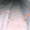
Victaulic Style 77 flexible couplings are
installed on the riser lines in the Petronas
Towers in Kuala Lumpur, Malaysia.
Also taking into account the maximum Delta T that the piping would experience, as well as the building creep, the engineer calculated the amount of movement that would occur within the main vertical riser. Based on these calculations, he made a decision to place a series of pre-gapped flexible couplings on the main vertical riser at each floor to accommodate total piping movement on a per-floor basis.
Several of the world’s tallest buildings have used the grooved system to meet their deflection needs. The Petronas Towers in Kuala Lumpur, Malaysia, are the second-tallest buildings in the world. To accommodate for structural movements and sway, contractors installed flexible couplings on the riser pipes in order to provide angular deflection.
In a recently completed Chicago high-rise, the engineer specified flexible couplings on the branch piping coming off the main risers because of their ability to provide a solution which allowed the pipe to grow, shrink and sway. Several Victaulic flexible couplings placed in a series were used to accommodate the deflection of the branch movement as the riser moves up and down.
The Bottom Line
Structural designs that include grooved mechanical pipe joints, such as rigid and flexible couplings, will alleviate the challenges faced in accommodating for settlement and deflection.In addition to the benefits in reduced footprint and added design flexibility, grooved mechanical joints assist in the creation of a durable and easy-to-maintain structure for clients. Contractors benefit from alleviated scheduling pressures and labor challenges due to the ease of installation with grooved mechanical joints. Grooved mechanical joints also decrease or eliminate the need for welding, which can significantly affect the safety on a job and through the life of a structure.
Engineers, owners and contractors can save time and increase a structure’s lifespan by planning for deflection and accommodating settlement in the design phase. Grooved mechanical pipe joints, whether rigid or flexible, offer a fast, space-saving alternative to welded joints.
