Figure 1.
As 2009 unfolds, there are many concerns about how the HVAC industry, especially the portion associated with new construction, will fare in the months (years?) ahead. America appears to have reached a point where a retracting economy and unstable energy prices have driven building owners to reexamine priorities.
The frills and energy-related complacency that were more easily absorbed in construction budgets only a few years ago are giving way to pragmatic choices about the efficacy of the building, its appeal to future tenants, its long-term impact on the environment, and its cost of operation.
One technology benefiting from this reexamination of priorities is geothermal heat pump systems. Although certainly not new in the HVAC industry, these systems offer a set of attributes that makes them well suited to the current situation:
1. They can be quickly switched from heating to cooling or vice versa as the needs of the zone change.
2. In commercial buildings, they take advantage of load diversity (e.g., a common situation in commercial buildings in which there are simultaneous demands for heat and cooling in different zones).
3.Their efficiency, in well-matched applications, lets them deliver heat at a unit cost that’s significantly lower than provided by other fuel options.
4. They harvest the majority of their heating energy from “phase delayed solar energy” (e.g., solar heat stored in the earth for several months), and, thus, can legitimately be classified as a renewable energy system. Congress recently made this “official” through wording in the economic stimulus legislation.
5. They are complementary to electrical energy produced by clean-energy sources such as photovoltaic systems, wind power and hydropower.
6. Since they only require electricity as a “fuel,” they lend themselves to evolving electrical procurement and demand side management strategies such as time-of-use rates, real time pricing, and “smart grids.”
7. They can “amplify” the efficiency of a combined heat and power generator driven by natural gas, propane, or biofuels.
8. They are well matched to low-temperature heating loads such as radiant floors and domestic water heating (or preheating).
9.They create virtually zero on-site emissions.

Figure 2.
Source Solutions
The lower temperature “source” water for a geothermal heat pump system can come from a variety of sources:All of these sources are used in residential systems. However, a closed-loop earth heat exchanger (burying tubing or lake plate) is the most common source solution for commercial systems. It largely eliminates potential concern over water quality (e.g., potential to create corrosion, scaling, biological contamination, etc). It also eliminates concerns of water quantity (e.g., the possibility that adequate source water is not available due to seasonal changes in water table depth, etc.)
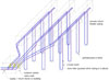
Since many commercial buildings have limited land around them, one of the most common types of earth heat exchanger is a “well field,” as illustrated in Figure 1.
An array of vertical holes, usually six inches in diameter, are bored in land adjacent to the building - often under what eventually will be a parking lot. A U-tube heat exchanger, usually fabricated from high-density polyethylene pipe, is inserted in each borehole, and then firmly grouted in place with an injected mixture of sand and bentonite clay.
The individual U-tube heat exchangers are then manifolded together with reverse return horizontal piping. The exact arrangement depends on the load requirements of the system, available space, pipe sizing, and depth of borehole. In many systems, subgroups of parallel-piped U-tubes are routed to an accessible “vault” where they are each fitted with isolation valves.
Individual circuit valves allow portions of the ground loop system to be purged or isolated from the system in the rare event that a repair is required. Larger piping is routed from the vault to the building’s mechanical room. In some systems, the parallel subgroups are each routed into the building and then fitted with isolation valves.
In North America, most earth loops are currently fabricated with high-density PE3408 SDR-9 or SDR-11 tubing. All joints in the tubing, or between tubing and fittings, are done using butt fusion or socket fusion. The ends of the tubing and fittings are heated to their melting point and then forced together. The resulting bond, when properly executed, is stronger than the original tubing.
In Europe, and to a lesser extent in North America, earth loops are also being fabricated from PEX tubing. Fusion joining is not possible with PEX, so special hydraulically-applied fittings are used. Individual circuits are commonly routed to interior manifolds, where they can be purged in the same manner as radiant panel circuits.
Another heat source option is a “lake plate” heat exchanger. This arrangement of 304 grade stainless steel plates is connected to polyethylene tubing and then submerged in a large pond or lake.
Each of the lake plate exchangers is rated to supply a nominal 60-ton (720,000 Btu/hr) heat pump system. The large surface area and high conductivity of this heat exchanger allow for a relatively compact design relative to a drilled well field or thousands of feet of horizontal trenches. Lake plate exchangers obviously require a large body of water near the building. They also may require the approval of government agencies associated with protecting such bodies of water. They should also be supported so that any accumulating silt does not cover the plates.
In cold climates, it’s imperative to evaluate the ability of the body of water to supply the required load through the heat exchanger. The combination of a small pond, a large heat exchanger, a large and sustained heating load, and heat pumps capable of operating at sub 32ºF fluid temperatures is asking for trouble. Design software is available from manufacturers to evaluate these situations.

Figure 3.
Moving Inside
Once inside the building, the system typically transitions to rigid piping materials, including steel, CPVC, and polymer composites. Flow passes through standard equipment such as an air/dirt separator and redundant “lead/lag” circulator set. The distribution piping within the building is usually constructed as a reverse return loop located in overhead mechanical plenum, as shown inFigure 2.Each heat pump forms a bridge between the supply and return mains, and is equipped with a balancing valve and isolation valve. Reinforced rubber hose sets are used to connect each heat pump to the distribution mains. This reduces vibration transmission.
In most systems, flow passes through all heat pumps whenever the main building loop circulator is operating (which is typically 24/7). When an individual heat pump is active, its compressor, blower, and possibly its reversing valve, are turned on.
The most common heat pump configuration in commercial GSHP systems is called a water-to-air (W/A) heat pump. Water is the heat transfer media between the heat pump and the building loop, while heating or cooling is delivered to the building by forced air. An example of such a “unitary” W/A heat pump (e.g., all major components contained in one enclosure) is shown inFigure 3.
Load Diversity
In most commercial GSHP systems, any heat pump on the distribution system can operate in the heating or cooling mode at any time, depending on the needs of its zone. This is beneficial in larger buildings that often require cooling of interior zones, even in winter, while perimeter zones operate in heating mode.Water temperature in the building loop increases as the heat of rejection from heat pumps operating in cooling exceed the heat of absorption for units operating in heating. In winter, this tends to keep the building loop slightly warmer, which improves the performance of heat pumps operating in heating. In summer, when all heat pumps are cooling, building loop temperature will rise significantly. Designers must ensure the ground loop is adequately sized to dissipate this heat. Maximum heat rejection is often the controlling factor in sizing ground loops for commercial projects.
The “extended range” heat pumps now used in commercial geothermal systems are capable of operating at incoming source fluid temperatures down to the mid 20ºF range. In Northern climates, where systems operate in heating-dominated conditions for several months, designers must evaluate the ground heat exchanger for minimum operating temperature. This temperature might even be a few degrees below 32ºF, and, thus, the ground loop (and perhaps the building loop as well) would need to operate with an antifreeze solution.
Under such conditions, the surface of the building loop piping could drop below the dewpoint of the interior air, and condensation would form. In such situations, the interior distribution system piping should be insulated and vapor sealed. The lower thermal conductivity of polymer and composite tubing makes it less prone to surface condensation relative to metal piping. However, every system should be evaluated for specific materials and operating conditions when determining if interior piping insulation is necessary.

Figure 4.
Decentralized Approach
Other design options for commercial GSHP systems include layouts where each building zone is equipped with one to three heat pumps. These units are then connected to vertical U-tube heat exchangers in boreholes located directly outside that space. An example of this concept is shown inFigure 4.This approach lets each zone function independently, and would not be affected by situations that might force a centralized system to be fully turned off during service. This approach requires more hardware within each zone, including details for bringing the earth loop piping to the heat pump(s), and for filling/purging this piping.
Another limitation of this approach is that it doesn’t take advantage of load diversity. As such, it is best applied in buildings with envelope-dominated loads.
On the Horizon
With ECM-based variable speed circulators now available in North America, look for even more optimized hydraulics on commercial GSHP systems. An example is use of 2-way on/off zone valves that close off a branch flow path through an inactive heat pump and allow the circulator to settle to a lower speed and lower power consumption.A related option is using a modulating valve to maintain a specific temperature change across the heat pump evaporator or condenser of each heat pump. We will discuss these and other new options for commercial GSHP systems in more detail in Part 2.

