
Issue: 12/03
Although hydronic radiant floor heating can be incorporated into many types of buildings, it's often a "perfect match" for garage-type buildings with bare concrete slab-on-grade floors. Some examples include vehicle maintenance buildings, aircraft hangers and fire stations.
For starters, the concrete slab is already part of such buildings. Making it into a radiant heat emitter is simply a matter of adding underside insulation and tubing. This keeps the cost per square foot to a minimum. Secondly, in a well-planned system, the tubing is well protected from damage under the concrete. Another plus is that bare slabs operate at relatively low water temperatures. This allows heat sources such as condensing boilers and geothermal heat pumps to attain high efficiency. It also allows for compact distribution piping, as will be discussed shortly. Finally, since people don't walk around barefooted in such facilities, designers can allow more variation in floor surface temperature and thus reduce cost through wider tube spacing.
Long Distance Travel
Larger buildings often require manifold stations to be located far away from the mechanical room. One-way distances of 200 or more feet are not uncommon. Given the expanse of such systems, designers should carefully consider the options available to transport the heat generated in the mechanical room out to the various manifold stations. Design requirements such as zoning different parts of the building, supplying different water temperatures to different manifolds, and providing for constant circulation also have to be worked into the design of the distribution system.The latter feature--constant circulation--is often desirable for heated slab floors in garage-type facilities. It allows redistribution of heat from interior slab areas to typical "cold sinks" such as the floor area just inside large overhead doors, or the wet floor under a vehicle shedding melted snow and ice. In combination with the huge thermal mass of a large floor slab, constant circulation also provides excellent protection against perimeter freeze-up in the event the heat source is inoperable.
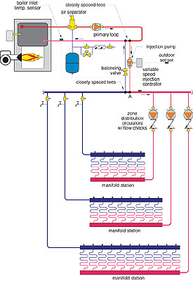
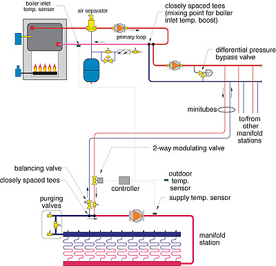
Figure 1 depicts one design option for a system that supplies three independently controlled zones, all operating at the same supply water temperature. The system is supplied by a conventional gas- or oil-fired boiler. Mixing is done in the mechanical room. Water at the mixed supply temperature is then piped to each manifold station using separate zone circulators.
With this approach, the flow rate to each manifold station is based on the design temperature drop of the manifold station. A typical range for this temperature drop is 15 to 25°F.
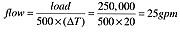
For example, assume the designer needs to provide 250,000 Btu/hr to a large manifold station where the supply water temperature is 110°F and the blended temperature from the return manifold is 90°F. The temperature drop is thus 110 - 90 = 20°F. The flow rate needed to supply this rate of heat transport at a 20°F temperature drop can be found using Equation 1.
This flow rate requires a minimum tube size of 1.5 inches to keep flow velocity in the range of four feet per second. A 2-inch tube might also be considered based on head loss requirements.
Although it's certainly possible to use 2-inch copper tubing between the mechanical room and a remote manifold station, this is not an inexpensive solution. The choice of distribution tube size also affects the volume of the system, and thus the size of the expansion tank, as well as the quantity of any antifreeze that may be added.
If the mixing device used in this system operates on outdoor reset control, and if properly set, there should be flow through the tube circuits most of the time. However, if a thermostat is turned down several degrees Fahrenheit for a night setback, the zone circulator will stop, as will the flow through the tubing circuits. During a long, cold night, water in tubing located just inside a large overhead door could freeze under such conditions, even though plenty of heat remains within the interior portions of the slab. The freeze protection benefit of constant circulation is not achieved.
Thermodynamic Opportunities
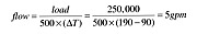
If the heat source supplying the heated slab is a boiler capable of operating in the temperature range of 160 to 200°F, a tremendous opportunity exists for designers who recognize and take advantage of basic thermodynamics. The opportunity at hand is transporting high temperature water to a given manifold station, performing the mixing at the manifold station, and then returning relatively cool water back to the mechanical room. The underlying thermodynamics are simple: The flow rate between the mechanical room and manifold station is inversely proportional to the temperature drop between the supply and return piping. Thus, if the supply temperature to the manifold station was 190°F, and the return temperature from the manifold station was 90°F, the flow rate required to transfer the previously assumed 250,000 Btu/hr can be found using Equation 2.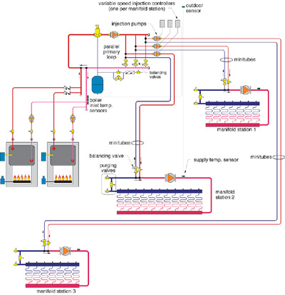
This approach is known as a "minitube" distribution system. An example of a three-zone mini-tube system is shown in Figure 2.
Notice that flow of hot water to each manifold station is regulated by a variable speed injection pump. This allows each manifold to operate with a different supply water temperature if necessary. It also allows for constant circulation within the manifold circuits.
In a typical minitube system, the distribution circulators at the manifold stations would be turned on when the outdoor temperature drops below a preset value where heating is deemed necessary. They would remain on during the heating season, even during periods where no heat is being supplied to the manifold. Constant circulation at the manifold also maintains accurate feedback from each supply temperature sensor to its associated injection mixing controller.
The primary loop in this system is split into three parallel crossovers. These allow the same water temperature to be available to each injection pump. The closely spaced tees in each crossover are the beginning and ending points for each minitube circuit, and eliminate any flow interference between the injection pumps. The balancing valves in each crossover allow the flow rate in each to be proportioned to the loads served by each manifold station.
A balancing valve is installed in the return injection riser from each manifold station. When the hot water flow is controlled by a variable speed injection pump, this valve is set so the injection pump will operate at full speed under design load conditions. When injection flow is regulated by the two-way modulating valve, the balancing valve is set so the modulating valve is fully open at design load. These adjustments ensure maximum rangeability of the control system, and thus precise control of supply water temperature.
Minitube systems inherently improve the rangeability of variable speed injection mixing systems. When variable speed injection mixing is done using short injection risers, a throttling valve must be installed in the return riser to remove a significant portion of the pump head. This is necessary to force the circulator to operate at full speed under design load conditions, and thus utilize the full range of speed control. In a minitube system, the vast majority of the head loss occurs due to fluid being carried through the minitube piping.
Since the manifold station circulator is not responsible for flow between the mechanical room and manifold station, it may be possible to use a smaller circulator. This reduces both initial cost and life cycle operating cost.
- The small minitube distribution piping also loses less heat to surrounding air than would larger diameter distribution piping of equivalent heat transport capacity. However, the supply minitube piping should always be insulated to minimize heat loss.
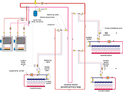
Reverse-Return Parallel Primary Loop
Another possible piping approach is shown in Figure 4. It combines a two-pipe reverse return primary loop with injection mixing. The two-pipe system would typically travel overhead around the perimeter of the building. A crossover bridge would be installed above each manifold station. A balancing valve is installed in each crossover to prevent overflow. A closely spaced set of tees within the crossover would connect the injection risers to the manifold station below. Either variable speed injection or two-way modulating valves could be used as the injection flow control device. The tube size of the mains could again be relatively small if designed to operate at a high temperature drop.
This design trades off more primary loop piping for short injection risers. Since the latter piping is usually smaller and less expensive, the primary loop routing should be carefully selected to minimize footage of larger diameter tubing and fittings.


