Author’s Note: This article is written with the final, proposed changes to the complete National Fire Protection Association (NFPA) 99 Code For Health Care Facilities not yet totally approved. The revisions to the code are complete internally, but have not been approved by the body of the NFPA members at their annual meeting. It is believed that approval will be granted, but revisions will not be officially published until they’re approved. Although this code is being published in April 2009, it will have a 2010 date. Therefore, this code will not be adopted by authorities until 2010. The information in this article is based on some of the changes that have been approved by the HEA-PIP Committee, of which I am a member.
Also, for purposes of this article, the term “levels” has been replaced by “category,” which is a recently approved revision. The design of dental facilities generally fall into two categories: installation into a health care facility such as a hospital, and installation into those smaller facilities that are considered stand alone. The governing document for both facilities is NFPA-99, Code For Health Care Facilities.
The figures presented here are from the annex of the code. The diagrams are not intended to imply any specific arrangements of components. Alternative methods and equally compliant arrangements are permitted if they meet the intent of the diagrams and the text of NFPA-99.
All information in this article pertains only to dentist offices, not any other health care facility. This article will only review the design considerations of the dental systems, namely compressed gases and dental vacuum. Information regarding installation, alarms, testing and verification are outside the scope of this article.

Figure 1.
Compressed Gases
The most often used gases are compressed air, nitrogen, oxygen and nitrous oxide. Compressed air and nitrogen are used separately as a drive gas to power pneumatic dental tools. Compressed air is used to quickly dry surfaces for examination, bonding and other treatment. For an illustration of an air compressor or nitrogen drive arrangement, refer toFigure 1.As a replacement for drive gas for tools, nitrogen supplied from cylinders is sometimes used. For use in dental offices, all gases are considered as Category 3.
Dental offices intended to be installed within health care facilities must have all gas systems completely separate from all other gases except at the source. The systems must not be connected to any other piping except those specifically intended to be used for the dental office.
Any stand alone facility is permitted to have storage of individual gases less than 3,000 cubic feet (90 m3), each at normal temperature and pressure. Except where stored in a Department of Transportation-listed cryogenic container, a total of 5,000 cubic feet each (150 m3) of gas is permitted.
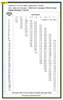
Table 1.
Using any anesthesia gas for dentistry is not permitted. Any anesthesia given must be by needle and administrated by a dentist or doctor.
Required Pressure and Flow Rate.Dentist offices use both high- and low-pressure gas. This pressure is adjustable at each chair or at the service outlet. The generally required pressure for high-pressure systems, such as that required for drills, etc., is 50-100 psig (350-700 kPa) and a flow rate of 2 scfm (57 L/min). Low-pressure compressed air is used for dental hygienists and laboratory purposes, and generally has a required pressure of 30-40 psig (210-280 kPa) with a flow rate of 3 scfm (85 L/min).
Diversity Factor.The approximate diversity factor to be used is suggested as follows. This assumes the worst case.
No. of outlets Simultaneous use factor, %
4 100
5-10 75
11 & over 50
Sizing.Sizing for all compressed gas is the same and is based onTable 1, which lists the system pressure loss in hundreds of feet. The initial system pressure is assigned to be a figure of 55 psig. The generally used allowable system pressure loss is 10% of the assigned pressure. This gives the entire system an allowable total friction loss of 5 psig.
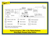
Figure 2.
Also, there are 10 outlets at 2 scfm per outlet and a 50% diversity factor, which equals a 10 scfm Adjusted Flow Rate. A 1/2-inch minimum pipe size must be used.
Now, go to Table 1 and find the row called Adjusted Flow Rate scfm. Read down to find the number 10, then across it until you find a figure of 1.1 or less. At the top of this column is the required pipe size.
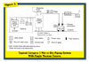
Figure 3.
Dental Vacuum
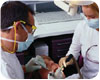
The dental vacuum system provides a suction system for the removal of fluids and suspended residue from oral cavities during operative and regular dental procedures, and also for removal of airborne dust in laboratories.When used in surgical suites, this should be considered a life support system. If a patient is under anesthesia, they may not be able to communicate to the dentist that accumulation of fluids may cause choking.
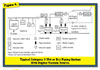
Figure 4.
As mentioned earlier, the use of gaseous anesthesia agents in a dentist’s office is not permitted. Nitrous oxide is, however, used for relative analgesia. Relative analgesia is a state of sedation and partial block of pain perception produced in a patient by the inhalation of concentrations of nitrous oxide not sufficient to produce loss of consciousness. General anesthesia is produced by the inhalation of concentrations of a gaseous agent that will render a patient unconscious.
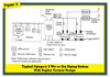
Figure 5.
For an illustration of a simplex vacuum pump with a liquid holding tank, refer toFigure 3. For an illustration of a duplex vacuum pump with a separator, refer toFigure 4. For an illustration of a duplex vacuum pump with a waste holding tank, refer toFigure 5. For an illustration of positive drainage of an air/waste separator, refer toFigure 6.
A separator removes liquids and suspended solids from the vacuum airstream. It should be placed on the patient side of the pump to remove liquids before they enter the pump or on the exhaust line to prevent discharge of liquids into the environment. The separator should have an overflow, which is either manual or automatic. For vacuum systems used only in laboratories, a cyclone separator may be provided.
Vacuum Pressure.The vacuum pressure for various systems are as follows:
Dental Surgery 5 to 8 inHg
General Dentistry 5 to 7 inHg
Laboratories 5 to 9 inHg
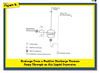
Figure 6.
Saliva ejector 2 to 3 scfm (depending on the tip)
High volume ejector 5 to 10 scfm (used to remove drill water)
Hygienist 5 scfm
One dentist and one hygienist 15 scfm
Laboratory 20 to 30 scfm
This is necessary to capture a wide variety of dust from grinding machines using a “fishmouth,” which has a large, open end.
Diversity Factor.There is no generally accepted method or criteria for determining the diversity factor for dental vacuum. Since each facility is different, it is prudent to anticipate the largest usage possible. The best method will be to ask the owner of a facility what would be the largest possible simultaneous use factor. Information obtained from successful working systems in existing facilities and from designers/installers of dental equipment has been used to establish the following general criteria for a combination of both dentists and laboratory.
1 to 2 chairs 100 percent
3 to 4 chairs 75 percent
5 to 10 chairs 50 percent

Figure 7.
1. The method to determine the equivalent run is the same.
2. The maximum pressure drop for the entire system must be 1 inHg.
3. The same method must be used to find the loss for 100 ft. of pipe.
4. UsingFigure 7, find the adjusted flow rate at the left side of the figure. Read horizontally to the right to a point where it intersects the vertical line showing the allowable loss for 100 ft. The pipe size will be found by reading up to the closest diagonal line, indicating a pipe size in inches. Disregard the alternate diagonal line indicating the velocity.
I would like to thank the NFPA for extending me permission to use illustrations that appear throughout this article. It is important to note that this material does not represent the official and complete position of the NFPA on the particular subject to which the material refers. The reader should consult the specific code or standard concerning the subject to which the material refers in order to fully understand the NFPA’s position on the subject.