John Siegenthaler's been designing hydronic heating systems for 25 years, and he still comes across little nuances that when ignored can bring a system that is 99.9% correctly designed and installed to a virtual standstill.

Issue: 1/03
It never ceases to amaze me how much there is to know about hydronic heating. I've been at it for 25 years, and still come across little nuances that when ignored can bring a system that is 99.9% correctly designed and installed to a virtual standstill. Others simply erode the potential operating efficiency of the system.
This month I've assembled a list of some important design errors to avoid.
1. Don't select control valves solely based on pipe size.
Most control valves regulate heat output by varying the flow rate of a constant temperature water stream flowing through a heat emitter. This is a highly non-linear process. Small changes in flow can lead to substantial changes in heat output, and vice versa.
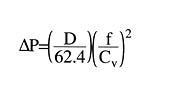
The pressure drop through the control valve in relation to the overall pressure drop through the branch is crucial for proper control. For stable control, at least 50% of the branch circuit's pressure drop should occur across the control valve when it is fully open. To determine the pressure drop of the valve (in its fully open position), one needs the valve's Cv value. This value can then be used in Formula 1 to calculate the pressure drop.
Formula 1, Where:
DeltaP = pressure drop (psi)
D = density of the fluid (at average system temperature) (lb/ft3)
f = flow rate (gpm)
Cv = flow coefficient of valve (gpm)
A given size valve body can have different Cv values depending on the diameter of the valve seat. Smaller seats result in lower Cv values. These Cv values are listed in the technical data sheets for the valves. Think of it this way: The valve's pipe size is selected based on what it connects to, but the valve's ability to perform as a heat regulator depends on its Cv value.
|
| FIGURE 1 |
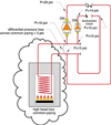
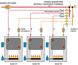
2. Don't allow flow through unfired boilers.
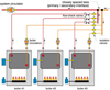
It makes no sense to add heat to a stream of water using one boiler, then pass that stream through another unfired boiler where some of that heat is dissipated. Multiple boiler systems should be piped and controlled so flow through the boiler is limited to times when the boiler is firing (or is in a thermal pre-purge or post-purge mode). The preferred arrangement, especially when condensing boilers are used, is to pipe each boiler in parallel with the other, as shown in Figure 1. This provides the same inlet temperature to each boiler, and allows total flow isolation when needed.

|
| FIGURE 2 |
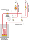
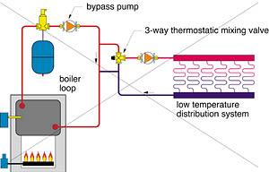
3. Don't count on a bypass pump to properly protect a boiler against flue gas condensation.
The ability of a bypass pump to properly boost the inlet water temperature to a non-condensing is usually limited by transient operating conditions in the system. For example: If a 200,000 Btu/hr is coupled to a radiant slab with a design load of 200,000 Btu/hr, the laws of thermodynamics allow a scenario where a bypass pump can boost the boiler's inlet water temperature high enough to prevent flue gas condensation. A possible schematic is shown in Figure 2. If the load remained steady, all would be fine. The trouble is that when a high thermal mass load is increasing in temperature, it has a voracious appetite for heat. A cold slab can remove heat from a warm water stream at three to four times the normal steady state rate. If this is allowed to occur, those same laws of thermodynamics dictate an immediate, and in many cases deep, drop in water temperature as the system seeks to find a new equilibrium between input and output. Under these conditions, a boiler bypass pump can only stir the contents of a rapidly cooling boiler.
Proper protection necessitates a mixing control system that senses and reacts to decreasing boiler temperature by limiting the rate of heat flow to the load. Most modern mixing control systems provide this capability. Still, I've seen a lot of piping schematics in recent months that need this protection and are not detailed for it.
|
| FORMULA 2 |
4. Don't needlessly oversize expansion tanks in radiant systems.
Most expansion tank sizing methods assume all system water reaches some maximum operating temperature simultaneously. This is essentially impossible since some of the water is passing through distribution piping and heat emitters where it gives up heat and drops in temperature. When all the water in the system is within a temperature range of say 20 degrees F, the error introduced by this assumption is small. The resulting tank size is also conservative, and if there's one thing most engineers gravitate to, it's conservative design.
However, in systems where the fluid temperature varies over a wide range, the conservative design methods often add considerable and unnecessary cost. A large (bare slab) radiant floor heating system is a good example. In such a system, the vast majority of the system water is contained in the floor circuits and seldom sees temperatures above perhaps 110 degrees F. A small percentage of the system water volume is contained in the piping and components on the boiler side of the mixing device. Depending on how the system is designed and controlled, this water may see a temperature of perhaps 180 degrees F.
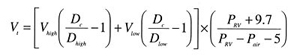
A proper tank sizing procedure should account for the combined expansion of both the high- and low-temperature portions of the system. Formula 2 can be used to find the required volume of a diaphragm-type expansion tank based on dividing the system volume into low- and high-temperature proportions. When applied to a large low-temperature radiant floor system, the reduction in required expansion tank capacity is substantial.
Formula 2, Where:
Vt = minimum required tank volume (gals)
Vhigh = volume of fluid contained in the higher temperature portion of the system (gallons)
Vlow = volume of fluid contained in the lower temperature portion of the system (gallons)
Dc = density of the fluid at its initial (cold) temperature (lb/ft3)
Dhigh = density of the fluid at the maximum operating temperature of the higher temperature portion of the system (lb/ft3)
Dlow = density of the fluid at the maximum operating temperature of the lower temperature portion of the system (lb/ft3)
Pair = air-side pressurization of the tank (see Formula 3) (psig)
PRV = rated pressure of the system's pressure relief valve (psig)
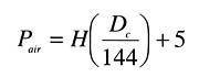
Formula 3, Where:
Pair = air-side pressurization of the tank (psi)
H = distance from inlet of expansion tank to top of system (ft)
Dc = density of the fluid at its initial (cold) temperature (lb/ft3)
|
| FORMULA 3 |
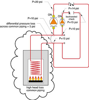
5. Don't combine pumps of widely different capacity on a common header system.
Consider the piping shown in Figure 3a. If the common piping between the headers has high flow resistance, the pressure drop across this piping (created by the larger circulator) may be higher than the shut-off differential pressure of the smaller circulator. Although the latter might be running, there will be no flow through it. Instead, the differential pressure across the headers will back seat the check valve in the circuit with the smaller circulator.
If large and small pumps need to operate simultaneously and deliver water from the same source, it's better to pipe them using a parallel primary/secondary system, as shown in Figure 3b.
|
| FIGURE 3A |
6. Don't apply a circulator near the ends of its pump curve.
The intersection of the system head loss curve and the pump curve of the selected circulator determines the operating flow rate in the piping circuit and the differential pressure across the circulator. Ideally, this intersection should be in the middle third of the pump curve, as close to the maximum efficiency point as possible.
Setting up a situation with extremely low head loss will force the pump to operate low on its curve. Not only does the efficiency plummet, the amperage goes up, possibly to the point of overloading the motor.
Forcing the circulator to operate high on its curve also sheds efficiency. Furthermore, the high differential pressure increases the thrust load on the bearing and may lead to flow noises in the system, especially when several zone valves are closed.
|
| FIGURE 3B |
7. Don't count on manually set mixing valves to provide stable water temperature control.
I like to refer to manually set mixing valves as "dumb valves." They may be of the finest quality materials and construction, but without a brain, they're seldom doing what is expected of them.
If the temperature and flow rates of both water streams entering the valve did not change, the valve would mix as expected. Unfortunately, this is almost never the case. Because loads change in the distribution system and the boiler heats up and cools down, most heating systems operate in almost perpetually transient conditions. Most folks who have lived with one realize that a simple shower valve can't react to changing flows or temperatures. The same is true for a manually set mixing valve in a heating system. To allow the valve to handle these conditions, it needs an actuator and controller.
|
| FIGURE 4 |
8. Don't build "microloading" into your systems.
There have never been more ways to subdivide a heating distribution system in zones. Given the propensity of zoning methods and hardware available, it's not uncommon to find a low mass, fixed firing rate boiler with a heating capacity of say 150,000 Btu/hr connected to a distribution system having perhaps a dozen zones. Many such systems have controls that fire the boiler when any of these zones call for heat. The result can be a 150,000 Btu/hr heat generation rate combined with a 5,000 Btu/hr heat dissipation rate, and four or five gallons of water in between to soak up the excess Btus. You probably don't need your calculator to speculate about how long the boiler will run in this scenario.
The solution is to: 1) Install a properly-sized buffer tank between the fixed output boiler and the zoned distribution system, or 2) Use a modulating boiler capable of tracking the load and adjusting heat generation accordingly.
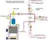
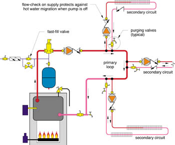
9. Don't forget to specify purging valves in all secondary circuits.
The closely spaced tees at a primary/secondary interface are specifically for "uncoupling" the pressure differential on one loop from another. While this is desirable during normal operation, it does not allow a strong purging flow in the primary loop to induce an equally effective purging flow in the secondary circuits. Without a means of purging each secondary circuit, it can literally take hours to displace air from the system when putting it into service. I suggest a ball valve and hose bib at the return side of each secondary circuit (see Figure 4). With the ball valve closed, the hose bib opened, and the fast-fill valve open, water from the primary loop can quickly drive the bulk air out of each secondary circuit.
10. Don't forget that hot water still likes to go up.
In all the years I've been involved with hydronic heating, I have never designed a pure "gravity flow" system. I've always counted on a circulator to turn on and push heated water through the intended path. I suspect many of the current generation of hydronic designers fall into the same category.
From this perspective, it's easy to forget about buoyancy-driven flow. Easy to overlook the fact that heated water "wants" to rise, and will do so if given the opportunity. Call it what you will--thermosiphoning, heat migration, or my personal favorite, "ghost flow." This unintentional flow of heated water in a hydronic system usually leads to problems such as warm radiators on a hot summer day, nuisance tripping of P&T valves, or indirect water heaters that set up their own convective loop through system piping and use it to release heat when nobody's looking (e.g. the pump is off).
Remember that the idea is to make heated water move when and where you want it. To hold the control reigns tightly. Doing so requires careful "imagineering" of what hot water will attempt to do in your system when the pumps are off. Be sure to include the necessary flow-checks, thermal traps, or other details to keep a lid on those Btus until they're needed.
I'm sure every hydronic system designer reading this article could add to this list, as could I. We've all made--and hopefully learned from--past mistakes and field observations. Avoiding the particulars described here will go a long way in helping to prevent "repeat offenses."

