
Issue: 8/03
The oldest existing records on file indicate that the General Assembly of the State of Pennsylvania authorized first class cities, which included Philadelphia, to enact rules and regulations governing the installation of plumbing and the examination and licensing of plumbers. This dates back to June 30, 1885.
The next substantial plumbing code enacted under this authority was January 1, 1912. Needless to say, it has been revised many times since then in order to continuously modernize and update the plumbing code.
The single stack, also commonly known as a wet vent system, is based on the theory that the drain lines will be of sufficient size to accommodate the three factors involved in any drainage system: solids, liquids and air. The single stack system used in Philadelphia was developed based on this theory.
The Philadelphia Single Stack
The Philadelphia Single Stack plumbing system does not require, nor does it depend on any special type of drainage or vent fitting. Any conventional type of drainage or vent fitting--such as a merion fitting, combination wye and eighth bend (single or double), sanitary tee (single or double), taped sanitary tee (single or double), long 1/4 bend with or without tapings, etc.--is permitted, as long as that particular material is in compliance with the Philadelphia Plumbing Code. In fact there is a no-hub cast iron soil pipe manufacturer that makes a fitting that they have named "The Hubless Philadelphia Single Stack Fitting." This fitting is available in several configurations, such as having two 4" outlets opposite each other, with the option of having four 1-1/2" outlets, two on each side, opposite each other. Having such a variety of fittings available only increases the flexibility and cost reduction of the installation in multi-story buildings. There are no restrictions regarding the levels at which small fixture waste lines enter the soil or waste stack, as long as the fittings in the stack are drainage fittings and are acceptable in accordance with the code.
A water closet may be eight feet from a vented stack or vented horizontal main without requiring an additional vent. Other plumbing fixtures may be 12 feet from a vented stack or vented horizontal main without requiring an additional vent. In the case where the outlet of a floor-mounted water closet is not more than four feet from the stack, you may use a long 1/4 bend with two 1-1/2" tapped outlets. The outlets can be used to connect a lavatory and a tub if they are within 12 feet and will not require an additional vent. You also have the option of utilizing the other fittings noted. As you can see, the flexibility this system offers can often result in installation cost savings of up to 40% in multi-story buildings such as hotels and apartments, because additional venting is not required.
Piping for Hotels
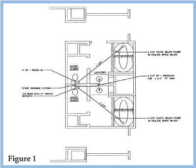
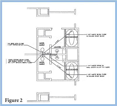
Two basic piping sketches have been prepared to indicate simplistic piping options in hotels. Almost all hotels are designed with the bathrooms located back to back, with a common service chase between them. In Figure 1, the stack fitting can be either a double combination or a double sanitary tee, with two 4" outlets opposite each other. The 1/4 bend (closet bend) has two tapped outlets, one for the tub and one for the lavatory. In Figure 2, the stack fitting can be the same as chosen above, but the closet bend has only one tapped outlet for the tub. Now, by using a double tapped outlet above the floor for the lavatories, you eliminate coring and fire protecting of two penetrations through the floor. You also eliminate more expensive pipe hangers and working overhead. The stack pipe and fittings are service weight no-hub cast iron with no-hub couplings, and the drain piping for the tub and the lavatory is DWV copper with DWV wrought copper drainage fittings and solder joints.
I would recommend that you contact the Philadelphia Department of Licenses and Inspection, Plumbing Division, (215) 686-2450 and (215) 686-2451, and obtain a copy of "The Philadelphia Plumbing Code." The code will offer you various options in piping design, additional venting, pipe sizing charts and much more detailed information.

Sanitary and Storm Drainage
Plastic pipe made of ABS and PVC is only permitted to be installed in buildings containing dwelling units. These buildings shall consist of from one to four families and shall not exceed three stories in height. Basements are not considered a story.In all other buildings, the underground sanitary or storm water pipe and fittings under the building shall be service weight cast iron bell and spigot with lead and oakum joints. Sanitary, storm water and vent pipe and fittings aboveground shall be cast iron bell and spigot with lead and oakum joints, or cast iron no-hub with no-hub couplings, or DWV copper tubing with copper drainage fittings and solder joints. You are not permitted to use DWV copper tubing for urinal drains; type "K" copper must be used.
Most of the city of Philadelphia has "Combination Storm and Sanitary Drainage Systems." The main drainage pipe in the street conveys both the sanitary and the storm drainage water from the buildings to the city's plant. Rainwater from the roof of a building is not permitted to dump on grade and must be piped. Also, secondary roof drainage is not required by code.
Now, let us understand how a combination storm and sanitary system is designed. It is rather simple. First, you design the sanitary system connecting all the horizontal branch lines (in a multi-story building) to the vertical sanitary stacks. The stacks continue down through the building to the lowest level and connect to the horizontal main drain, located at the ceiling of the basement or under the first floor slab. All pipes are sized by adding the total number of drainage fixture units assigned to each individual plumbing fixture connected to each horizontal branch line, which in turn is connected to each stack. The stack size is dependent upon the total number of drainage fixture units that are connected to it and extends full size up through the building. So, if the total number of drainage fixture units requires an eight-inch stack, then that stack is eight-inch up through the building, and it becomes an eight-inch vent above the highest plumbing fixture and continues up through the roof.
This holds true as long as all of the plumbing fixtures are within the allowable distance of the sanitary stack. (Note: No additional venting is required under this condition.) If the plumbing fixtures are beyond the allowable distance, additional venting is required.
The sanitary drainage stack does not change size because the drainage increases with the additional load connection at each floor. Remember that in this system, the vertical sanitary drainage stack serves two purposes: 1) to handle drainage, and 2) to serve as a vent. If a building is 75 feet in height and not more than 160 feet in height above grade level at the curb, the vertical soil or waste stacks connected to the house drain or to any of its branches shall be one size larger; should the building height exceed 160 feet, then the stack shall be increased two sizes. The horizontal main drain increases in size as each vertical stack is connected. The size of all horizontal sanitary drainage pipe is determined by two factors: 1) the total number of drainage fixture units (DFUs), and 2) the slope of the pipe. In the case of storm water, the two factors are: 1) square footage of roof area assigned to each roof drain, and 2) the slope of the pipe.
When the building is more than three stories high, all plumbing fixtures on the first floor are connected to the horizontal main drain and not the vertical stack. This is done to prevent hydraulic jump, which in turn would pull the water seal in the plumbing fixture trap. Fixtures above the first floor are permitted to be connected to the vertical stack.
The layout of the main horizontal sanitary drain has been completed and sized. Now we have the rainwater conductors (RWC), which have been connected to the roof drains, have been run down through the building, and are going to be connected to the main horizontal sanitary drain. The square footage of the drainage conveyed by each RWC is noted. We now convert the sanitary drainage fixture units by multiplying each DFU by seven, thereby converting the drainage fixture units to square foot of roof drainage. We now add the converted DFUs to the square footage of roof drainage and size the horizontal main drain. Since the rain water conductors are connected to the main drain, a trap must be provided at the base of each RWC. Cleanouts must be provided at the base of each sanitary stack and each RWC.
When designing for a one-story building such as a motel, the main horizontal sanitary should be located within the proper distance of the plumbing fixtures to eliminate additional venting. In this instance, we calculate the size of the main starting from the last plumbing fixture connections and increasing the size of the main drain when additional fixtures are connected, unlike with the vertical sanitary stack. With the last set of plumbing fixtures being a bathroom group, the vent for the main house drain could be a four-inch pipe, even though the main sanitary drain may be an eight-inch line. The storm system is connected to the sanitary main, and total sizing is calculated as described above.
When plumbing fixtures are installed beyond code limitations, such as eight feet for a water closet or 12 feet for other types of plumbing fixtures, or when a horizontal branch line has more than one plumbing fixture connected to it, a vent is required. Materials for vent piping are the same as for drainage piping. Vent pipe sizing is determined by the length of the vent and the number of DFUs connected.
This article is intended to present a very brief overview of how simple it is to design a Single Stack Plumbing System and also to show why it is so very inexpensive to install.