Like most "little" things, the final few feet between the branch line and the sprinkler head in a fire protection system usually gets little, if any thought. But as increasing numbers of new and retrofit commercial projects are proving, these few feet can make a noticeable difference, both initially and over the life of the property. Using flexible connections in place of traditional hard-pipe armovers pays dividends that at first blush would seem out of proportion for such a relatively minor detail.
Flexible connections install quickly, have fewer points of potential failure, have an installed cost that is at least competitive with hard pipe, and are very accommodating of building, use or code reconfigurations. This article discusses the physical attributes of flexible fire sprinkler connections, and the financial/economic aspects of specifying flexible connections rather than hard-pipe armovers.

History of Flexible Fire Sprinkler Connections
The first viable flexible fire sprinkler connections were developed by FlexHead Industries of Holliston, MA, for semiconductor manufacturing facilities. Initially designed for exhaust-duct protection, the technology was then adapted for suspended ceilings in cleanrooms. The flexibility of the connection eliminated concerns about armover joint leaks or particulate generation caused by building shifts or seismic activity, as well as providing fast-track construction and the ability to easily accommodate future space changes. The high-quality, welded stainless steel construction and a custom-designed fit-up also contributed to eliminating particulate generation, which is an important concern in the ultra-filtered cleanroom environment.
Several years ago, the technology was adapted for use in suspended ceilings commonly found in commercial projects. Currently, a handful of manufacturers offer flexible sprinkler connections that employ various designs, materials and construction approaches. Typically, the units consist of a threaded pipe nipple to connect to the main or the branch feeder line, flexible connecting hose in standard lengths, a reducing fitting that the sprinkler head is attached to, and a mounting bracket that attaches to the ceiling grid (Figure 1). The mounting brackets are designed so that the sprinkler head accurately hits center-of-tile with no adjustments or calculations required of the installer. Usually, the brackets also allow for vertical adjustments of the heads to achieve consistent, specified exposure through the ceiling tile.
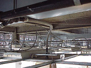
Regardless of design and construction, flexible connections offer some advantages over traditional hard-pipe armovers. For instance, they involve fewer joints between the feeder line and the sprinkler head, which both eliminates most of the handwork that a hard-pipe armover requires and also substantially reduces the number of potential sources of leaks. Also, because the mounting brackets typically take the guesswork out of hitting center-of-tile, fussy adjustments are eliminated. Field reports also indicate that flexible connections enable installers to quickly and easily overcome unexpected obstacles, such as ducts or wall segments. In many cases, reconfiguration of the system to accommodate space or code changes is also much faster because the connection doesn't need to be disassembled and re-installed. Assuming the hose is long enough, it's simply a matter of depressurizing the system, repositioning the mounting bracket and reconnecting the sprinkler head assembly.
Flexible Approaches
Within the realm of flexible sprinkler connections, however, there are several comparison points to consider that affect cost (initial, installed and lifetime) and performance. These include the material used, the design, and the degree of factory vs. onsite assembly required.
The most obvious feature, and an important delta, is the corrugated hose. Both the inside diameter and the material used affect friction loss, which can vary among different brands by more than 350% over a six-foot hose length. In practice, as systems are sized from the heads back to the main--regardless of whether they are hard pipe or flexible--the friction loss values can impact the size of the mains. One-inch "true" inner diameter stainless steel hose exhibits the best friction loss, producing equivalent-length values similar to that of a hard-pipe armover, as well as providing superior resistance to corrosion over time. Flexible sprinkler connection friction loss data is expressed in equivalent lengths of one-inch Schedule 40 pipe, and should be included in the hydraulic design calculations the same as a valve or fitting
Both the strength of the hose and its resistance to reverting to its original shape under pressure are greatly enhanced by the use of a braided sheath. The fact that only braided hose can pass the stringent testing that Factory Mutual requires for its certification (see UL/FM Testing Sidebar) illustrates its importance. As with the hose itself, the sheath material used also affects the performance.
Another consideration is the way the various elements of the system are joined: hose, fittings, and sprinkler head. Some flexible systems use o-ring joints between the hose and the fittings; others use welded joints. For the reducing fitting that attaches the sprinkler head, some manufacturers swage pipe and then thread the reduced inside diameter. Other manufacturers machine their fittings from solid stock, which produces very consistent tolerances and durability.
The different design and manufacturing approaches also produce different onsite experiences and can affect the economics of the installation and lifetime costs. Some systems are delivered fully assembled and pre-tested at the factory. Others are delivered as component parts that must be assembled onsite. Such systems require more labor for installation and more materials management and handling onsite, though they still deliver installed economic and performance profiles that are superior to traditional hard-pipe armovers. Factory pre-testing is not possible when the components are assembled onsite, so it's necessary for the contractor to verify joint integrity.
The final piece of a flexible sprinkler connection assembly is the mounting bracket that attaches to the suspended ceiling grid. All mounting brackets share the advantage of accurate center-of-tile placement, which eliminates the need for the installer to calculate where the drop should go, as in hard-pipe installations. However, some mounting brackets are single piece units, and others comprise sub-components that require onsite assembly. As with other field-assembled components, this approach to the mounting bracket requires more installation labor and can be more susceptible to potential building shifts and seismic activity.
Figure 2
The Economics of Flexibility
The cost of materials often leaps out in an evaluation of a flexible sprinkler system, and for obvious reasons. All else being equal, stainless steel technology can't compete with black pipe if the price of material is the only criterion. But in the case of sprinkler systems, all else is not equal, and a quick look at the overall picture shows that, just like performance, the economics of flexible systems are much better than traditional hard pipe.
First, the installed cost of flexible systems is at least cost-competitive with hard pipe, but the material/labor ratio is different (Figure 2). Using a conservative benchmark, a typical installer can complete at least four flexible installations in the time it normally takes to do one hard-pipe armover. Field assessment reveals that the actual ratio is even better than this. In the case of "difficult" installations, it can be easier as well. Why is this?
Factory-assembled flexible installations require only three steps:
- Connect to the feed line;
- Install the mounting bracket; and
- Install and adjust the height of the sprinkler connector in the mounting bracket.
These three steps do not require high skill, so contractors can concentrate their better-skilled (and usually higher-paid) people on other parts of the job where the skill requirements are higher. The installation consistently and by design hits center-of-tile, including projects where that aesthetic has not necessarily been specified. Conversely, even in standard installations, hard-pipe armovers require multiple, labor-intensive joints and trips up and down ladders to position the drop. They also usually require additional labor-intensive adjustments to hit center of tile. Even if the flexible connectors are field-assembled, the labor savings can be significant enough to offset the additional materials cost.
A non-obvious cost factor is where the sprinkler installation fits in the construction schedule. Almost always, sprinkler installation comes in the final stages, when many trades are converging to finish the job. Not surprisingly, the scheduling and deadline pressures are also greatest at this stage.
Typically, the sprinkler drops are installed prior to the ceiling grid being put in place. Then the installer must return and complete the panel cuts and final sprinkler installation and adjustment, working around the grid and in-place panels. Frequently, the scheduling of other trades is affected by the sprinkler installation, and vice versa, because of the normal sequence of events in final construction.
Flexible connections introduce greater flexibility and speed into the schedule for two reasons: drop installation goes much faster (because there's only one joint per drop, connecting to the feed line), and the installation and final adjustment of sprinkler head height can be completed faster. The reduced time required for these two phases frees time in the overall scheduling. Additionally, after the initial connection to the feed line, the flexible drops can be secured out of the way until the final installation. This means that other trades--ceiling grid installers, for example--don't have to work around hanging hard pipe, so the work environment is safer, and the possibility of workers bumping into pipe and disrupting the joints is eliminated.
Summary
The initial net effect of using flexible fire sprinkler connections is a shortened and more efficient end-stage construction schedule, which can enable faster time-to-occupancy. Over the life of the property, flexible fire sprinkler connections will also make space reconfigurations or code updates easier and faster, which also can affect occupancy time and lower cost. Service work is also considerably easier and faster, and costs less. These are among the reasons why well-known companies have specified flexible connections for all of their properties. Flexibles are also currently being specified in a number of new construction and retrofit projects, including schools, department stores, office buildings, airports, and a growing number of other commercial projects.
Hydrostatic Pressure Test
Eight samples are subjected to a hydrostatic pressure of five times the rated working pressure of 175 psi (1205 kPA) to 875 psi (6030 kPa) for a period of one minute while filled with water. The assemblies shall show no signs of distortion or leakage.
Vibration Test
Two samples are mounted in the pendant position on a test fixture attached to the table of a vibration machine. The samples are to be then pressurized with air at a pressure of 175 psig (1.21 MPa) and vibrated vertically and horizontally for 60 hours. The amplitude of the vibration is to be 0.04 in. (1.02 mm) and the frequency to be continuously varied between 18 and 37 hertz. The test samples shall show no signs of leakage, distortion or change in length and be subject to the Hydrostatic Pressure Test at 500 psig following each mode of vibration.
Friction Loss (Equivalent length of pipe)
Water is to be discharged in the intended direction of flow through a sample extended to its full length. The water pressure is to be initially set at 7 psig (0.048 MPa) and then varied in 5 psig (0.035 MPa ) increments over the range of 10 psig (0.069 MPa) through 100 psig (0.69 MPa), and the flow rates in gallons per minute are to be recorded at each pressure. The friction loss shall be equated to the length of 1-in. Schedule 40 pipe using the values averaged.
Water Hammer Test
A sample hose assembly is subjected to 3,000 applications of pressure surges from 50-500 psig at a rate of 60 cycles per minute and shall show no signs of deterioration or leaking. After successful completion of the test, the hose assembly is subject to the Hydrostatic Pressure Test at 500 psi (3.45 MPa) and shall show no signs of deterioration or leaking.
Mechanical Strength Test
A sample assembly incorporating mechanical stops subject to torsional forces shall withstand a torque of 60 pound-feet (81 N.m) applied to the outlet. The test samples shall show no signs of deformation, fracture, or leakage and be subject to the Hydrostatic Pressure Test at the rated working pressure of 175 psi (1205 kPa).
High Temperature Test
Two samples are to be subjected to the Hydrostatic Pressure Test. The samples are then exposed to an ambient temperature from 325 to 375 degrees F (163-191 degrees C) for 90 days. Following the exposure, the samples are subjected to a hydrostatic pressure of 500 psig for one minute. The test samples shall show no signs of distortion or leakage.
Freezing Test
Two samples shall be connected to a 4-in.-long, 1-in. nominal size Schedule 40 pipe and filled with water and exposed to an atmosphere of minus 20 +-10 degrees F for 24 hours. The test samples shall show no signs of leakage and be subject to the Hydrostatic Pressure Test at 500 psig (3.45 MPa).
Salt Spay Corrosion Test
Three samples shall withstand an exposure to a salt spray atmosphere in accordance with ASTM B117-94 for 10 days without exhibiting any incipient corrosion.
Hydrostatic Strength Test
A sample hose assembly shall withstand a hydrostatic pressure of four times the rated working pressure of 175 psi (1205 kPa) to 700 psi (4825 kPa) for five minutes. The test samples shall show no signs of rupture, cracking, permanent distortion, or deterioration of performance characteristics.
Vibration Test
A sample assembly is secured to a vibration table with the end fitting in a vertical plane and the hose bent 90 degrees at its minimum bend radius. The test sample will be filled with water and pressurized to 90 psi (620 kPa) while being subjected to the vibration conditions from 0.020 in. (0.51 mm) to 0.070 in. (1.78mm) total table stroke at 18 to 37 Hz for a 25-hour period. The assembly shall show no signs of deterioration and be subject to the Hydrostatic Strength Test.
Friction Loss (Equivalent length of pipe)
Samples of each length shall be tested using the test apparatus for determining discharge coefficient (K-Factor). Flow measures shall be taken at 10 psi (70 kPa) increments from 15 to 175 psi (105 to 1205 kPa) using an open sprinkler with a normal discharge coefficient of K=5.6 or K=8.0 and with the sprinkler mounted to the sample. The average friction loss shall be equated to the theoretical length of nominal 1-in. diameter Schedule 40 pipe, using a flow of 30 gal/min (155 L/min).
Pressure Cycling Test
The test sample shall be filled with water and bent 90 degrees with the threaded end fitting restrained and the hose unrestrained on a flat surface at its minimum bend radius and subjected to 20,000 cycles of pressure varying from 0 to 175 psi (0 to 1205 kPa) at a rate of approximately 6 cycles per minute. The test samples shall show no signs of deterioration and be subject to the Hydrostatic Strength Test.
Fatigue Test
The test is conducted in accordance with Section 8.3 of the ISO Standard 10380-1994. A minimum of two hose assemblies shall be subjected to 50,000 cycles of repeated flexing at a rate of 5 to 30 cycles/min at twice the minimum bend radius while pressurized to their rated working pressure. The test samples shall show no signs of deterioration and be subject to the Hydrostatic Strength Test.
High Pressure Flow (Head Deployment)
An assembly shall be fitted with a sprinkler and secured in a commercial ceiling frame assembly. The sprinkler shall be operated using a suitable heat source. A minimum of seven tests shall be conducted with pressures ranging from 10 psi to 175 psi (69 to 1206 kPa) in approximately 30 psi (210 kPa) increments. The test sample shall show no signs of deterioration or its attachment.
Vacuum Test
An assembly shall withstand a vacuum of 26 inHg (660 mmHg) for a period of five minutes, during which time there shall be no collapse or leakage. The assembly shall show no signs of deterioration of performance characteristics and be subject to the Hydrostatic Strength Test.
")