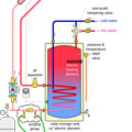
Figure 1.
Most contemporary solar thermal systems fit into the broader category of hydronic systems. They just happen to use solar collectors rather than a boiler as their heat source.
As such, the same principals that govern air collection and removal in conventional hydronic systems also apply to solar thermal systems. Much of the hardware used for these purposes is also very similar.
Figure 1shows a typical closed-loop solar thermal system of domestic water heating. This system circulates a propylene glycol solution between the collector array and the heat exchanger in the storage tank whenever there is heat available for collection.
All closed loop solar subsystems require a “purging group” consisting of a fluid inlet valve, a fluid outlet valve and a third valve in between. The third valve can either be a ball valve or a check valve.Figure 2shows a close-up of both options.
In some systems, the three valves that make up the purging group are installed as individual components. In others, these valves are part of a preassembled solar circulation station. You also can buy a complete “purge and fill” valve assembly that has the same functionality as the individual valves shown in the upper portion of Figure 2. An example of such a product is inFigure 3.
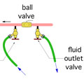
Figure 2.
If a ball valve is used between the fluid inlet and outlet valves, it must be closed during the filling and purging process. The check valve does not require any adjustment during filling and purging. The pressure created by the entering fluid is sufficient to hold the disc or flapper of the check valve in its closed position during purging.
Fluid is pumped into the circuit through the fluid inlet valve. The fluid travels around the solar collection circuit and eventually exits through the fluid outlet valve. A hose routes the exiting flow back to the container from which fluid is being transferred into the system.
For effective purging, the fluid should move through the circuit at a flow velocity no less than 2 feet per second. At this speed, the fluid can push most of the bulk air volume in the piping in the downstream direction. Eventually, this air is ejected through the fluid outlet valve and carried back to the fluid container through a hose. That hose should be held in a position that prevents air bubbles from being “jetted” to the bottom of the container where they could be drawn back into the fluid supply hose or pump.
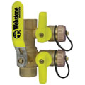
Figure 3, A Webstone “purge and fill”
valve assembly.
Purging Engines
Several different types of pumps have been used to fill smaller solar subsystems. They range from small submersible pumps to “drill pumps.” An example of the latter is shown inFigure 4.A typical drill pump could likely handle purging of up to six parallel-pipe collectors. Larger collector arrays will require higher-capacity purging pumps.
Figure 5shows an example of a purging assembly that is relatively easy to construct and can generate substantial flow and differential pressure for purging larger collector arrays. It uses a swimming pool pump ranging from 1 to 2 horsepower to provide considerably more “oomph” for purging. This assembly also can be used to fill and purge residential-scale geothermal earth loops.
When purging begins, the fluid level in the container will drop quickly, and only air will be exiting the fluid outlet valve. Within a few seconds, this condition gives way to a combination of air and liquid “spitting” out the discharge hose. As additional air is entrained and returned to the container, the exiting stream transitions to what appears to be an air-free stream of liquid.
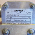
Figure 4. A Zuwa drill pump.
Next, close the fluidoutletvalve and allow the purging pump to increase the static pressure in the circuit. The extent of pressurization depends on the purging pump used. This pressurization will likely take only a few seconds. When there is no further increase in system pressure, as observed on the system’s pressure gauge, close the fluidinletvalve and turn off the purging pump.
If the piping circuit is not at or slightly above the required pressure, fluid may be added using a positive displacement hand pump such as that shown inFigure 6.
The final pressurization of the circuit should be based on the manufacturer’s recommendation. Some manufacturers prefer higher static pressures to help protect the fluid from vapor flash at elevated temperatures.
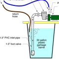
Figure 5.
Patience Please
At this point, most of the “bulk air” will have been removed from the circuit. However, molecules of oxygen, nitrogen and the other gases that constitute air remain dissolved with the cool fluid that has just been added to the system. This dissolved air needs to be “cooked” out of the fluid as it passes through heated collectors.A float-type air vent located at the very top of the system is the best way to capture this air. My preference is to use a vent with a 1/2-inch-size piping connection, rather than the typical 1/8 or 1/4-inch-size vents often found in other hydronic systems. The larger piping size is more effective in capturing air bubbles.
This vent sits above a vertically oriented ball valve at the very top of the circuit, as seen in Figure 1 above. The valve should remain open for several days during which the system is operating and air bubbles are likely being formed within the collectors. After this time, the ball valve should be closed to protect the vent from potentially high stagnation temperatures. The ball valve should be specifically rated for solar applications, or otherwise rated to withstand service temperatures of at least 350º F.
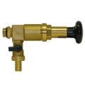
Figure 6. A Paw positive displacement
hand pump.
Annual maintenance checks on the system should include verification of system pressurization. When necessary, system pressure can be boosted using a hand pump and a short length of hose. Loosely connect the free end of the hose to the fluid inlet valve. Pump some fluid through the hose and let it leak out of the loose connection. This helps displace air in the hose and hose connection. Tighten the connection, open the fluid inlet valve and pump in fluid while watching the pressure gauge.
When the desired pressure is reached, close the fluid inlet valve and disconnect the hose. Put a written tag on the fluid inlet valve indicating the date fluid was added, the type of fluid added and the final pressure gauge reading.
As a side note, all antifreeze solutions used in solar thermal systems should be tested for pH and reserve alkalinity on an annual basis. Use the fluid manufacturer’s guidelines to determine if the fluid needs additional buffering.
You now have simple and effective ways to get fluid into and air out of a solar collector circuit. A properly deareated collector circuit will operate with very little detectable noise, and provide good heat transfer for many years.

