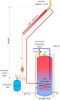
Figure 1.
Solar thermal systems, like hydronic systems, operate best when pressurized. Increasing pressure raises the boiling point of the fluid, adds to the Net Positive Suction Head Available (NPSHA) of the system to help suppress circulator cavitation, and helps vents eject accumulated air from the system. I’ve also found that circulators are slightly quieter when operating under pressure.
One question that often arises in solar thermal system design is: “What’s the correct pressure for the collector circuit?” This month, we’ll take a look at the physics behind this question.
Let’s start with the typical system configuration shown inFigure 1. The collector subsystem forms a closed, fluid-filled loop filled with an antifreeze solution. For our analysis, assume the fluid is a 40% (by volume) solution of inhibited propylene glycol.
The relationship between absolute pressure and boiling point for this fluid is shown inFigure 2. Let me stress that the pressure shown on the vertical axis is absolute pressure (e.g., relative to total vacuum). Typical atmospheric pressure (14.9 psia) is shown, along with the corresponding boiling temperature of 219ºF.
As the pressure maintained on the solution increases, so does the boiling point temperature. For example, at 58 psia (about 43.3 psi gauge pressure) the solution has to reach 300ºF before it boils.
You can see that the vapor pressure curve gets progressively steeper at high fluid temperatures. In theory, it’s possible to maintain the glycol solution in liquid form at temperatures well above 350ºF (e.g., where the graph in Figure 1 ends), but the pressures are well above anything we want to deal with in typical HVAC systems.

Figure 2.
Given this situation, it’s reasonable to ask: Can the fluid in a solar collector be prevented from boiling under stagnation conditions by increasing its pressure? As usual, the answer begins with – it depends.
Let’s say you’ve calculated the maximum probable stagnation temperature of a particular collector to be 350ºF. Based on Figure 1, the fluid would have to be maintained at about 119 psia (about 104.3 psi gauge pressure). That’s a very high pressure to maintain in the collector. Furthermore, the pressure lower in the loop would be even higher due to static head.
Such pressures may exceed the ratings of the collectors and other components used in the system. These pressures are also significantly higher than the water pressure in a typical domestic system, and that may violate some mechanical codes.
The test pressures for various collectors can be found in the OG-100 ratings published by the Solar Rating and Certification Corporation (www.solar-rating.org). Collectors certified to operate at “street” pressure are tested at 160 psi. However, not all collectors fall into this category. Those that don’t are tested to 1.5 times the manufacturer’s rated pressure, with a minimum test pressure of 25 psi. For further information on collector testing, see the following Web site:www.solar-rating.org
The higher the thermal efficiency of a collector, the better it retains heat, and the higher its stagnation temperature (given the same ambient conditions). Higher stagnation temperature implies that higher pressure is required to suppress boiling under stagnation conditions.
Based on the properties of a 40% propylene glycol solution, I’ve concluded that increasing system pressure high enough to prevent vaporization in the collector during stagnation is not practical.

What to Do
So what happens when the collector approaches maximum stagnation conditions? Answer: Some of the fluid in the collector will vaporize. Next question: When this occurs, does the pressure relief valve on the collector loop open? Answer: It depends.If, when boiling first occurs, the majority of fluid in the collectors is pushed out of the collectors by a small amount of vaporization, andifthe system’s expansion tank is sized to accommodate this volume in addition to the thermal expansion of the collector loop fluid due to heating, then the pressure relief valve will not open.
We’ll get into sizing the expansion tank for a closed loop solar subsystem in the next column. However, these calculations require a known pressure relief valve setting, so let’s address that first.
I suggest the following procedure for selecting a pressure relief valve pressure:
Step 1:Verify if local mechanical codes applicable to solar thermal systems mandate a maximum pressure relief valve setting. If so, it’s obviously the benchmark.
Since it’s wise to include a safety factor, I suggest the maximum pressure at the location of the relief valve, under stagnation conditions, be 5 psilowerthan the code-allowed relief valve setting. This provides a margin against the possibility of the relief valve weeping fluid should system pressure teeter one or two psi less than the relief valve setting.
Step 2:Verify that all the components in the collector loop have a maximum pressure rating generously above this setting. In the absence of any code provision that requires otherwise, I suggest all components used in the loop have a pressure rating at least 1.5 times the rated opening pressure of the relief valve.
Step 3:Calculate the pressure at the top of the collector loop based on its height.
Step 4:For reference, determine the corresponding fluid boiling temperature in the collector based on the pressure determined in Step 3.
Here’s an example: Assume local code mandates a maximum relief valve setting of 50 psi, and that the vertical distance from the pressure relief valve to the top of the collector array is 25 feet.
The maximum pressure at the pressure relief valve will be set at the relief valve rated pressure minus 5 psi (45 psi).
The pressure at the top of the collector loop will be less, specifically:
The 33.7 psi is a gauge pressure. It converts to 33.7 + 14.7 = 48.4 psia (absolute pressure) at the top of the collector. The corresponding boiling point temperature from Figure 1 is approximately 287ºF.
If the code doesn’t specify a maximum relief valve setting, you might investigate the possibility of suppressing boiling in the collector to a higher stagnation temperature. This is essentially working the previous procedure in reverse.
For example, suppose we want to suppress boiling up to 300ºF at the top of the collector. The corresponding absolute pressure (for the 40% propylene glycol solution represented in Figure 1) is about 58 psia. The corresponding gauge pressure is 43.3 psi.
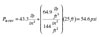
The pressure at the relief valve location, which is 25 feet lower in this system, would be:

Finally, check that the rated pressure on all components used in the loop is at least 1.5 times the rated pressure of the relief valve; in this case 90 psi.
In the next column, we’ll look at how collector loop pressurization, and the fact that vaporization is likely to occur in the collector during stagnation, effects expansion tank sizing. As some of you expect, the size of the expansion tank will often be significantly larger than what is used in a typical hydronic heating system.
