
What defines a “green” hot water distribution system? Ideally, such a system would minimize the waste of water, energy and time during all three phases of all hot water events in a given application. In addition, there would be an energy-efficient water heater or boiler, sized to the application, to make the needed hot water.
Figure 1depicts a hot water event. There is a delivery phase, a use phase and a cool down phase. We want the delivery phase to be short, the use phase to be whatever is needed to do the intended job and, once we turn off the tap, the temperature of the water in the pipes to cool down (unless we have done something special to prevent this, such as recirculation or electrical heat trace).
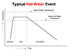
Figure
1. Source of all graphics: Gary Klein, Affiliated International Management,
LLC.
Assuming that the diameters of the pipe between the water heater and fixtures are selected properly, this would also minimize the volume of water in the pipe. All hot water fixtures and appliances would be located very close to the water heater or boiler. In virtually all cases, the hot water piping will be insulated.
At a minimum, this improves the performance during both the use (less temperature drop over a given distance at a given flow rate and pipe diameter) and cool down phases (more time between hot water events before the pipe cools down, particularly useful if there are clustered draws) of the hot water events.
However, I wonder how frequently we encounter this idealistic layout. We rarely see it in houses. Sometimes we see it in small multi-family or commercial buildings with a central plumbing core. It is rarely the case in larger buildings, but those are the ones we are asked to engineer the plumbing.
Recently, I looked at the plans for a 4-story addition to a building on a college campus that was aiming for LEED Platinum. There was reasonable, but not perfect, stacking and back-to-backing of the restrooms. There was only one location away from the main restroom groupings that had a significant demand for hot water, and it contained a shower. All of the other restrooms only had one or two sinks. No water heater (or boiler) location(s) were shown on the drawing.
My fear is that there will be a boiler installed in the mechanical room on the roof and that there will be a recirculation system installed to deliver hot water to the fixtures. Oh, there might be a 90%-plus efficient water heater or boiler installed, but the costs of operating the recirculation loop will be enormous compared to the actual hot water consumption. In my opinion, this is not a green hot water distribution system.
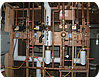
Figure
2. Photo shows three demand-controlled pumping systems, one for each wing of 12
units in a 3-story apartment building in San Francisco, CA, during major renovation.
The pump for each wing is activated by a flow switch. Each unit is sub-metered
for both hot and cold water and has its own demand-controlled pump activated by
time-delayed motion sensors. The three main pumps each run less than 1 hour per
day, and the pumps in each unit run about 15 minutes per day.
Improving Hot Water Distribution Systems: Some Strategies
Point-of-Use Water Heaters or Boilers. One strategy for improving hot water distribution systems is to install point-of-use water heaters (or boilers). Point-of-use is not about water heater size, it is about location relative to the fixtures and appliances. The water heater and the piping need to be sized to meet the intended loads.Small loads, such as intermittent use of hand sinks in restrooms located far apart from each other, are probably best served by individual water heaters. The same principle applies to larger loads, such as showers or janitorial closets. The water heaters could be storage tank, tankless or a boiler, but they must be sized for the intended loads.
The hot water distribution piping must be insulated. Remember that the cost of bringing power (electricity or natural gas) is generally large compared to the cost of bringing hot water piping, so the distance between hot water locations needs to be relatively large in order to justify the installation of additional water heaters. And, of course, the installations of both the water heaters and the piping must meet applicable codes.

Figure
3. Acceptable Wait Times Compared to Flow Rate and Pipe Diameter
Demand-controlled pumping systems are electronically controlled. They are activated on-demand by buttons or motion sensors (both wired or wireless) or by flow switches. After the relatively high-head, high capacity pump moves the water quickly through the piping, shut-off is automatic based on a rise in temperature of between 3 and 10 degrees F. Built-in safety mechanisms limit both the temperature in the return line and pump run time.
For a given layout of hot water locations, any one of these systems can be installed so as to optimize both the volume (length and diameter) of the recirculation loop and the volume (length and diameter) of water in the pipe from the recirculation loop to the fixtures or appliances.
Once the supply portion of the recirculation loop is filled with hot water, the waste of water, energy and time while waiting for hot water to arrive at a fixture or appliance is determined by the volume of not-hot water in the piping between the recirculation loop and the fixture.
I have noticed that at least one state’s health and safety code (that of California), states that: When fixtures are located more than 60 feet from the water heater, a recirculation pump must be installed in order to ensure that hot water reaches the fixtures at a temperature of at least 120°F. Wouldn’t hot water get to the fixture eventually? Does this allow for 59.9-ft.-long runouts from the recirculation loop to the fixtures? What is the allowable diameter of the runouts?
As to the first question, it would only get there if there was a relatively long hot water draw, from, say, taking a shower or filling a tub. Short, intermittent sink draws at faucets drawing 0.5 gpm might take many hours before hot water will get to the fixture. This is something we have experienced in conference hotels. As to the second and third questions, the rule does allow for 59.9-ft-long runouts, and it does not specify the diameter.
The problem is that large volume runouts mean that large amounts of water, energy and time are wasted waiting for hot water to arrive. In addition, during the use phase, for a given flow rate, the temperature of the water in large-diameter piping drops more quickly over a given distance.
Finally, during the cool down phase, while the temperature of the water in the runout drops relatively slowly due to the large diameter, once it has dropped below a useful hot water temperature, a relatively large amount of heat has been lost.
American Society of Plumbing Engineers' (ASPE) members will be familiar with the 100-foot compromise on the distance between a water heater and the fixtures before a recirculation system should be installed that was developed by the industry in the 1970s. (This amount is longer than the rule in California’s health and safety code.)
The dilemma is that minimal wait times are expected at all flow rates (seeFigure 3) and there are no acceptable times for the delivery of hot water for a flow rate of 0.5 gpm and any of the nominal pipe diameters in the table. This flow rate is typical of faucets in commercial facilities, and, in fact, is likely to be even lower for the portion of the draw that comes from the water heater due to mixing that occurs at the faucet.
For convenience, I will call the pipe serving one fixture a twig. (A branch line serves two or more fixtures or appliances, and a trunk serves many.) In order to bring the delivery time of hot water into the range of acceptable performance at low-flow rate draws, either the diameter or the length of the twig serving one fixture needs to be reduced, or some combination of both.
The performance of recirculation systems depends on (1) the method used to keep the temperature in the trunk line acceptable for use and (2) the volume of the water in the twigs. In order to keep the time-to-tap acceptable at low flow rates, the supply portion of the recirculation loop (trunk) needs to be located close to all fixtures.
This concept for optimizing hot water distribution system design is called Structured Plumbing®. A Structured Plumbing layout locates the trunk line such that the twig line contains no more than 2 cups of water (roughly 10 feet of 0.5 inch diameter piping) between the trunk line and each fixture or appliance. All hot water lines are insulated and the recirculation loop is demand-controlled. (Copies of the Structured Plumbing Guidelines are available on request from the author.)

Figure
4. Photo shows self-regulating electrical heat trace strapped to the copper
pipe and wrapped in insulation.
It is also possible to adjust the temperature upwards for sanitizing cycles during off-peak periods. Electrical heat trace systems do not need return lines, drastically reducing the heat loss of the hot water distribution system.
Insulation is extremely important for an electrical heat trace system to operate properly. Over many years, the manufacturers have learned that it is much easier to install their systems if there is equal heat loss per foot of pipe. This is different from the insulation schedule prevented in some energy codes, which specifies pipe insulation thicknesses that are not proportional to the nominal pipe diameter, resulting in unequal heat loss per foot. Following guidelines established in Germany for all hot water distribution piping, some recommend that the wall thickness of the insulation be equal to the nominal diameter of the piping. For example, if the nominal pipe diameter was 0.5 inches, then the wall thickness of the insulation would be 0.5 inches. 0.75 for 0.75, 1.0 for 1.0, etc.
As you can imagine, when the pipe diameter gets large, the insulation jacket also becomes quite large and then it becomes problematic for the pipe assembly to fit within the walls or floors. Given specific circumstances, such as a large-diameter trunk line with continuous flow of at least 1 gpm, it is possible to reduce the insulation to no larger than 2-inch wall thickness, or compensate by adding another line of heat trace, or both. Equal heat loss per foot makes it possible to simplify the control system and, therefore, lower installation costs.
Heat trace can be installed on just the supply portion of a recirculation loop (trunk), in which case the twigs will still experience hot water delivery time similar to those in a recirculation system. Alternatively, heat trace could be installed all the way from the water heater (or boiler) to each fixture, in which case the delivery time will be greatly reduced. They can also be installed in conjunction with a recirculation system.
For example, the recirculation loop could be installed in a vertical chase and the heat trace could be installed on the horizontal branches and twigs serving apartments on each wing. Electrical heat trace could also be used in a point-of-use water heating system, where hot water delivery time is critical whenever hot water service is required.
One of the biggest benefits of an electrically heat-traced hot water distribution system is that hot water delivery time can always be brought into the acceptable range, regardless of flow rate. In fact, it can be brought into the low end of the range by tracing the pipe all the way to where the twig exits the wall. However, the fact that heat trace can be used to dramatically reduce the delivery time is not a reason to otherwise ignore efficient hot water distribution system design.
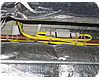
Photo
shows a junction between two sections of self-regulating electric heat trace.
The heat trace is mechanically strapped to the pipe. You can see 3/4 inch wall
thickness insulation on the 3/4 inch pipe in the background. Source: Craig
Drake, Tyco Thermal.
Conclusions
It seems to me that we need to think about hot water distribution systems differently depending on the application. I would also suggest that we need to measure the performance and hot water demand in a wide variety of applications so that we can better understand the level of performance needed, given modern fixtures and appliances. We also need to think about the water, energy and time consequences of each alternative with the goal of providing a desired level of performance that is most efficient.As of today, LEED has a methodology to get credit for improved hot water distribution systems in new homes (EA-7). There is nothing similar for multi-family or commercial buildings. Why not? Let’s get together and establish one.