What is a jockey pump and why does it carry that title? Picture a horse race. There is a small guy riding on top of (or above) a large horse. That small guy on the horse is referred to as a jockey. On a fire protection system requiring a fire pump, there is a small pump that maintains pressure above the pressure settings of the larger fire pump. Hence the name "jockey pump." The purpose of a jockey pump is to maintain pressure in a fire protection piping system so the larger fire pump does not need to run. A jockey pump package consists of a pump, motor and controller.
Two Types of Pumps
There are two types of pumps available for jockey pump applications. The preferable design is a centrifugal pump. The other type is a positive displacement regenerative turbine pump. A turbine pump appears to be the perfect choice as a jockey pump because it can generate high pressures at low flow rates with low horsepower. This is exactly what we are looking for in a jockey pump. However, a turbine pump operates on very close tolerances. If those tolerances wear out a few thousandths of an inch, the ability to generate enough pressure is lost.
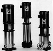
Examples of centrifugal jockey pumps.
Of greater concern is the ability of a positive displacement regenerative turbine pump to generate very high pressure if left running. This pump has the ability to exceed rated system pressures and burst pipes. The solution to this problem that works on paper is to install a pressure relief valve on the discharge pipe of the jockey pump. The thought behind this is that the valve will open at a preset level and dump excess pressure down the drain before it can cause damage to the sprinkler system. However, the reality is that most pressure relief valves are regulated by a spring that is exposed to the water in the system. The valves need regular exercise to keep them from becoming stuck closed. The relief valve on a jockey pump will never operate until the dangerous over-pressure condition occurs. Then the relief valve will most likely not open or open such a small amount that over-pressurization will still occur. A centrifugal pump is not dependent on tight tolerances and will merely churn at the highest pressure point on the curve.
Flow and Pressure
Whether a centrifugal or regenerative turbine type pump is used, it should be sized for low flow and high enough head to achieve the maximum fire pump discharge head. There are some existing design conditions that make the performance selection fairly easy. The flow must not exceed the flow capacity of a single sprinkler head, or the jockey pump will be incapable of maintaining pressure when a head opens up to fight a fire. The object is to overwhelm the jockey pump so the pressure continues to drop in the system, resulting in the fire pump starting. When the fire pump starts, it is usually wired to an alarm system that will bring the fire department. The jockey pump is usually not wired to alarms.
There is an additional flow restriction that reduces the capacity of the jockey pump even further. A sprinkler system has at least one butterfly-type flow switch. These switches respond to a flow as low as 10 gallons per minute. If the jockey pump flows at more than 10 gallons per minute at any point on the performance curve, it could trigger the flow switch and bring the fire department out on a false alarm. So, as a rule of thumb, the desirable flow rate for a jockey pump is around five gallons per minute. If the pump is capable of seven gallons per minute maximum and the operating point on the curve is three gallons per minute, the jockey pump will maintain pressure but it will not set off a flow switch.
Now we should talk about pressure. The jockey pump should be capable of generating the same pressure as the fire pump generates at churn or no flow. It is best to avoid a jockey pump that can generate much more than that because it could be flirting with the possibility of exceeding the rated system pressure.
There is an exception to every rule and here it is. If a sprinkler system involves any underground piping that will carry system pressure, leaks underground will occur. These leaks are very costly to find and repair. Therefore, the current thinking is to provide a jockey pump of some greater capacity than would be required if the entire system was above ground. Depending on the size of the underground system and an infinite number of strange system applications, jockey pumps as large as hundreds of gallons per minute have been used.
Power
Now that we have flow and pressure sorted out, the next question deals with power. I have yet to see a jockey pump that is not powered by an electric motor, so we will only deal with electric power in this discussion.
In some parts of the country, all jockey pumps are powered by three-phase motors. In other regions, single-phase motors are more widely used. Either way, the pump will function the same. There is a limitation to the performance of a pump powered by a single-phase motor. The horsepower required is dictated by the flow and pressure required. As either of these factors increases, so does the horsepower. Therefore, at some point, the performance exceeds the horsepower commonly available in a single-phase motor.
The other half of a jockey pump package is the controller. A three-phase controller will have a basic set of components consisting of a circuit breaker or fused disconnect switch, a contactor, overload protection, a pressure switch and a Hand/Off/Automatic selector switch, all housed in a metal enclosure. A single-phase controller could be as simple as a pressure switch and a toggle switch, or as complex as a three-phase controller. It depends on local codes and horsepower.
Sometimes, people try to find power for a jockey pump inside a fire pump controller. This is not acceptable. A fire pump controller is not to be used as a junction box or raceway. The proper source of power for a jockey pump is provided through a distribution panel that serves the building.
Piping
Piping a jockey pump is fairly simple. Water is usually provided from the same source as the fire pump, but it could come from some other source. The important thing to remember is that the suction piping and discharge piping must be arranged so the jockey pump or fire pump can continue to function even if the fire pump or jockey pump is isolated and out of service. The jockey pump piping should include an isolation valve on the suction and discharge piping and a check valve on the discharge piping. Of course, if a regenerative turbine-type pump is used, a pressure relief valve must be installed on the discharge pipe.
The sensing line is a half-inch non-ferrous pipe that connects the sprinkler system to the jockey pump pressure switch. There are two orificed unions or orificed check valves in the line to protect the pressure switch from hydraulic shock. NFPA 20 requires the sensing line to be connected between the jockey pump check valve and the jockey pump discharge isolation valve.
Setting Pressure Switches
Now that we have the jockey pump selected, wired and piped, it is time to set the pressure switches. As an example:
City pressure is 40 psi. The fire pump generates 110 psi at churn. So, the maximum discharge pressure is 150 psi (40 + 110 = 150). The city pressure could fluctuate somewhat, so we will assume a worst case scenario of 35 psi. That brings our theoretical maximum discharge pressure down to 145 psi. That is our jockey pump pressure switch shut-off point. Most pressure switches will not permit a differential between off and on of less than 15 psi, so our turn-on point of the jockey pump pressure switch will be 130 psi (145 - 15 = 130). We don't want the fire pump to turn on too close to the jockey pump settings because two separate pressure switches may wander a bit, so we will maintain a 10 psi spread. So, the fire pump will turn on at 120 psi. The same 15 psi differential determines the fire pump shut-off point at 135 psi. These settings will insure the fire pump can satisfy the pressure settings and shut off, as well as maintaining the system near the maximum pressure so hydraulic shock is kept to a minimum.
Weekly Testing
A fire pump is supposed to be operated weekly. While many people comply with this requirement, they may not perform the weekly test as fully as they could. Some people merely push the start button on the fire pump controller. Others purge the sensing line to simulate a drop in system pressure. Neither of these procedures fully exercise or fully demonstrate the fire pump room equipment. The jockey pump is not tested, proven or exercised with these approaches.
The better way of performing a weekly test is to open a main drain slowly. Watch the pressure drop on a system gauge. Observe if the jockey pump starts at the proper setting. Close the main drain. Observe if the jockey pump is capable of building pressure to the point that it satisfies the pressure switch and shuts off. Now open the main drain again and watch the jockey pump turn on. Open the drain a little more so the jockey pump can't keep up with the pressure loss. Observe if the fire pump starts at the proper pressure. Shut the drain valve. Check packing, bearings, casing relief valve and general operation. Either press the stop button on the fire pump controller, or let the minimum run timer time out and observe if the fire pump shuts down.
This procedure confirms that the jockey pump works, the fire pump works, the pressure settings of both pumps are proper and the system will function properly when that sprinkler head opens up to extinguish a fire. All equipment has been exercised. In an ideal world, the sprinkler system is completely watertight, every check valve holds 100%, and neither the fire pump nor the jockey pump will ever be called upon to operate. The only running time the pumps would ever get is during the intentional weekly test. But this is not an ideal world, which makes weekly testing of the pumps so crucial.
Jockey pumps play a very important part in the trouble-free operation of a fire protection system. If care is taken in the selection, installation and maintenance of the equipment, it should last for many years.
