Issue: 3/02
This article discusses how the decision was made to heat an addition to an existing house with a hybrid (in-floor radiant/baseboard) hydronic heating system. It was written by a practicing engineer and presents practical engineering analysis intended for fellow practicing engineers. The article also presents measured performance data from a side by side comparison of radiant and baseboard heat on the project.
Load Calculations and System Selection
The loads define the engineering characteristics of the project, so calculating loads is one of the first steps in any project. There is only one real way to calculate heat loss: Q (heat loss, BTU/hr) = U x A x delta. The competing methods are all simplifications or variations on that basic formula. A companion to this article, available onPME's Web site at www.pmengineer.com, describes some of the modifications proposed for radiant heating systems and explains why not to use them.Once loads have been calculated, the next step is to select a system type. This is when the designer decides whether to use hot water baseboard, in-floor radiant, a warm air furnace, a heat pump, etc.
Proponents of radiant heat claim many benefits over other types of heating systems. Some of those claims are truly attributable to radiant heat. Others result from comparing well-designed radiant systems to poorly designed other systems. A second companion to this article, also available on PME's Web site, compares functional aspects of perimeter baseboard and in-floor radiant heat.
Application to the Project
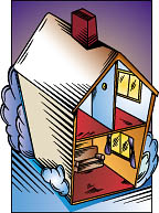
The project that precipitated this article is an addition to an existing house. It was (and is) heated by a gas-fired hot water boiler. The addition was to be heated by adding a zone to the existing boiler. The boiler was installed when the house was built (around 1958) and provided both space heat and domestic hot water. Since that time, the walls and ceiling were insulated, and a separate gas-fired hot water heater was installed. Both those changes reduced the load on the boiler. In addition, the new construction replaced two large, leaky windows with a well-insulated wall, reducing heat loss from the existing house. In light of those changes, the boiler was assumed to have enough capacity to support the new zone. If boiler capacity proved inadequate, money would be spent upgrading the envelope of the existing house rather than adding boiler capacity. The availability of boiler capacity and the relative ease of piping hot water over to the new addition quickly narrowed the heating system choices to hot water baseboard or in-floor radiant.The addition is built over a well-insulated (9 in/23 cm fiberglass batt/R-30) but unheated crawl space. The room is used as a home office, so the owner would spend many hours sitting at a desk. The crawl space is enclosed by foundation walls, and the band joist is caulked and insulated (R-30), so the crawl space stays warmer than the outside air. Nevertheless, the owner was concerned about discomfort (cold feet) from a cold floor surface. Avoiding that problem required either some type of in-floor heat, or insulating and heating the crawl space.
The proposed furniture layout also influenced the hvac system selection. The owner wanted free-standing bookcases. The wall space required for the bookcases limited the wall space available for baseboard heat. If bookcases were butted against baseboard, they would have to be modified to let air in at the bottom. The opening required for airflow would make the bottom shelf unusable.
The calculated heating load for the project came to 14.7 mbh (4.3 kW) composed of 9.9 mbh (2.9 kW) transmission loss and 4.8 mbh (1.4 kW) infiltration loss. Those values include a 10% safety factor and 15% for pickup after night setback. That heating load translates to 34.7 Btuh/ft2 (109.5 W/m2). That load density is higher than a typical house because the addition is relatively small. The addition has almost as much building skin area as a larger (wider) structure that would have 50% to 80% more floor area.
A heating load density of 34.7 Btuh/ft2 (109.5 W/m2) is difficult to meet with in-floor radiant heat and a carpeted floor. Therefore, an in-floor heating design for the project would require some form of supplementary heat. Conventional hot water baseboard was selected. Tubing in the ceiling or the walls could also have been used. Tubing in the walls would have to coordinate with the furniture layout. Since the owner rearranged the furniture after construction was complete, supplementary tubing in the walls might have been a poor choice. Tubing in the walls might also be susceptible to physical damage from activities like hanging pictures. That risk is actually fairly small because supplementary tubing in a wall usually runs only a few feet up the wall. Pictures are normally mounted higher on the wall.
After considering the relative costs for baseboard and in-floor radiant heat along with the need to avoid a cold floor surface, the addition was designed with a hybrid baseboard and in-floor heating system. The design philosophy was to maximize the amount of baseboard that would fit under the windows and a few feet to either side where bookcases would not be located and meet the balance of the load with in-floor radiant heat. The in-floor heat solved the cold floor problem and preserved wall space for bookcases. The room wound up with two 8-ft/2.4-m lengths of baseboard (one on each side) that deliver a total of 6.2 mbh (1.8 kW) at the design water temperature (145 degrees F/63 degrees C average) and flow. The rest of the capacity required for the project (8.5 mbh/2.5 kW) was provided by in-floor radiant heat. The resulting radiant heating density was a workable 19 Btuh/ft2 (60 W/m2) supplied to the room and an estimated 4 Btuh/ft2 (13 W/m2) of edge and back losses. The required capacity was provided with 153 degrees F/67 degrees C entering water and tubing spaced on 9 1?in (24 cm) centers.
On this project, the in-floor heat provided 58% of the installed heating capacity. Other projects might end up with other splits, and either baseboard or in-floor radiant heat could dominate.
Once the decision was made to incorporate in-floor radiant heat, the next decision was what type of in-floor system to use. The radiant system selected is a sandwich over sub-floor design. The driving factors that led to that choice on this project were:
- avoiding having to work overhead in a shallow crawl space;
- avoiding the need for special tools to install the tubing;
- flexibility in tube spacing;
- not having to complete the heating system before insulating under the floor; and
- the ability to use the same boiler water temperature as the baseboard in the main house, avoiding the need for a mixing valve.
Special Considerations for In-Floor Radiant Heat
As with any system type, in-floor radiant heat presents some unique design considerations.Capacity Limits
The first consideration is the limit on the amount of heat an in-floor system can deliver to the space. That limit is a function of floor surface temperature, which generally should not exceed 85 degrees F/29 degrees C. The 85 degrees F/29 degrees C maximum is based on comfort and keeps the floor surface temperature from exceeding typical skin temperature. Figure 9 in Chapter 6 of the 1996 "ASHRAE Handbook--Systems and Equipment" shows that an 85 degrees F/29 degrees C surface temperature translates to a heat flux of 30 Btuh/ft2 (95 W/m2) for a room temperature of 70 degrees F (21 degrees C) and an average unheated surface temperature (AUST) of 68 degrees F (20 degrees C). Depending on floor covering and the system water temperature, the maximum available heat flux might be less than 30 Btuh/ft2 (95 W/m2). For example, using Figure 9, a hardwood floor with staple-up tubing on 12 in/25 mm centers in a 70 degrees F/21 degrees C room reaches the 85 degrees F/29 degrees C surface temperature limit with approximately 145 degrees F/63 degrees C average water temperature. By comparison, the same system with a carpeted floor would require 180 degrees F/82 degrees C average water temperature to reach 85 degrees F/29 degrees C surface temperature. If the boiler water temperature setpoint is a typical 180 degrees F/82 degrees C, the average water temperature will ordinarily be 170 degrees F/77 degrees C, and a carpeted floor would deliver 29 Btuh/ft2 (91 W/m2).
Edge and Back Losses
Edge and back losses can be substantial and should not be overlooked. They increase the amount of heat that must be delivered to the panel, and they are a heat gain to the space below. On one project, an owner planned to install a refrigerated (55 degrees F/13 degrees C) wine room in the basement below his radiantly heated kitchen. Even with R-30 insulation under the floor, the 15 degrees F/8 degrees C temperature difference from the room above to the wine room added 450 Btuh/130 W to the cooling load for the 1000 ft2/93 m2 wine room. That heat gain had to be included in sizing the wine room refrigeration system.
Thermal Mass and Thermal Lag
Depending on the mass of the floor heating system, thermostat overshoot might occur. A heavy concrete floor with embedded tubing continues emitting heat for hours after the thermostat shuts off. Even a staple up or sandwich over sub-floor design has more thermal mass than conventional baseboard heat, so it continues emitting heat after the thermostat is satisfied. For that reason, radiant heat might be a disadvantage where precise temperature control is required or where the load changes rapidly.
Thermal mass and thermal lag considerations might limit the use of night setback control with in-floor radiant heating systems. The system might have to come back on hours before occupancy to reach occupied temperature at the scheduled time. Night setback is a powerful energy saving tool. The more thermal mass in the in-floor radiant heating system, the less suitable it is for night setback. That potential energy saving might not be practical to capture.
Radiant Heat Coordination and Installation Issues
Radiant heating systems present coordination and installation issues that differ from conventional hydronic heating systems and that vary with the in-floor heating system design.Tube in Slab Systems
A successful tube in slab system requires adequate insulation under the slab. The insulation must be installed early in the project, long before the hvac contractor is normally on the job. A successful tube in slab system needs a responsible person to see that the insulation is installed according to plans and specifications. The only practical remedy for omitted insulation may be to increase the radiant heating system capacity and accept excessive operating cost for the life of the building.
A tube in slab system requires selecting the hvac contractor before the concrete pour. On fast track jobs with conventional heating systems, the hvac contractor is often not selected that soon. The general contractor might not have the interest or skills to supervise the tubing installation in the slab.
After the tube is placed, it should be pressurized during the concrete pour. Otherwise, the weight of the concrete might collapse the tube. On a green field site, a pressurized water supply might not be available. While air can be used, air is dangerous if the tube breaks. Also, there might not be any electricity to power an air compressor during the pour and for several hours thereafter until the concrete cures and the tube is no longer at risk of collapse.
Installing the tube in the slab requires a firm architectural design. Changing rooms or moving partitions and appliances could be expensive if those changes would affect the tubing layout.
While those obstacles are not insurmountable, they are coordination issues for a tube in slab system that other system types do not face.
Staple-Up Systems
On a staple-up job, the tubing is attached to the underside of the heated floor. This arrangement avoids some of the coordination issues of the tube in slab system but presents coordination factors of its own.
Installing the tube requires working overhead, which no one likes to do. The problems of working overhead translate to increased cost and possible reduced quality or attention to detail.
As a practical matter, tube spacing is usually limited by the joist bay spacing. For example, with 16 in/40 cm joist spacing, tube spacing can be 8 in/20 cm, 5 1?in/13 cm, or 4 in/10 cm on center. Spacing of 10 in/25 cm on center is not practical. A zone that uses 8 in/20 cm spacing with lower water temperature is a more expensive installation than if 10 in/25 cm spacing were feasible.
A staple-up job generally requires holes in the joists to connect the tubing runs in each joist bay. While joists can accommodate some properly placed holes, holes compromise the structure.
The sub-floor and floor are thermal resistances between the tubing and the heated space. That increased thermal resistance requires either warmer water or closer tube spacing than a tube in slab design to deliver the same heating capacity to the space. Although raising the water temperature might save tubing (and money), spacing the tubes too far apart can lead to "striping." The room still heats adequately, but occupants tend to notice temperature differences across the floor surface.
As a general rule, regardless of spacing, a staple-up job requires warmer water than a tube in slab job. That warmer water temperature may be an advantage for a hybrid system. If the radiant and baseboard systems can be sized for the same temperature water, the radiant loop will not require a mixing valve and associated controls. Eliminating a mixing valve reduces both cost and complexity. Warmer water temperature also reduces the concern about flue gas condensation and might allow using a conventional boiler instead of the more expensive units designed to tolerate flue gas condensation.
Sandwich Over Sub-Floor, Including Lightweight Concrete Over Sub-Floor
Like a tube in slab job, a sandwich over sub-floor or lightweight topping slab over a sub-floor can accommodate any tube spacing. Tube spacing and water temperature can be adjusted and balanced to match job requirements. If the top layer of the sandwich is plywood or other poor heat conductor, the sandwich over sub-floor design will require the same higher water temperatures as a staple-up job with the same advantages and disadvantages.
Compared to staple-up, sandwich over sub-floor offers the advantage that the tubing contacts the flooring material on three sides compared to only one side for staple-up. The extra contact area should improve heat transfer from the tube to the floor.
The major installation and coordination issue for this design is planning and allowing for the additional floor height. With the lightweight concrete topping slab, the structural design must accommodate the added weight.
Performance and Data Analysis
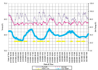
The hybrid in-floor/perimeter hot water baseboard project described in this article provided an opportunity to collect actual performance data and compare radiant and convective heating systems in the same room under similar conditions, including weather and occupancy.Figure 1 is a graph of room temperature, floor temperature, and outdoor temperature monitored with data loggers. It shows the benefit of in-floor heat in keeping the floor surface temperature warm. The floor temperature was measured by simply placing a data logger on the floor, so it is not truly the floor surface temperature but the air temperature with a half-inch of the floor. However, it shows generally what happens to the floor temperature. The data show that the floor surface temperature dipped well below the room temperature at the end of the longer off-cycles. Prolonged exposure to a cold floor surface leads to discomfort and occupant complaints.
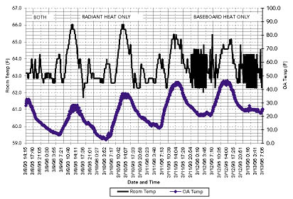
Figure 2 shows the results of a direct comparison between the in-floor and baseboard heating systems. To avoid introducing variables like pick up after setback and P+I control algorithms, temperature was controlled at a fixed setpoint using a simple, on-off, "round" wall thermostat. The system was first allowed to stabilize with both radiant and baseboard circuits active. Then the system operated with radiant heat only (baseboard valved off) for two days. After that, the radiant circuits were valved off, and the system ran for two days on baseboard heat only. The data lead to the following observations:
- The room temperature cycle time was much longer for the radiant system compared to the convective system. That not surprising observation is due to the greater thermal mass of the in-floor heating system (even a sandwich over sub-floor design) compared to baseboard. The longer cycle probably contributes to increased comfort. People are less likely to notice a 3 degrees F/1.5 degrees C temperature change that occurs gradually over a four- to five-hour period than the same 3 degrees F/1.5 degrees C temperature change that cycles five or six times in that same four- to five-hour period. The limits on temperature cycling and temperature drifts in ASHRAE Standard 55, Section 5.1.5, support that reasoning. This factor might be responsible for much of the claim of increased comfort with radiant.
- The in-floor radiant system exhibited considerably more room temperature overshoot than the baseboard system in the same room under roughly the same weather conditions. Modern, sophisticated controls might be able to reduce that overshoot.
- Looking at Figure 1 and Figure 2, along with the occupant's comments, reveals that the in-floor heat did a good job of avoiding a cold floor problem.
Unanswered Questions with Radiant Heat
In-floor radiant heat is a growing industry with numerous manufacturers and systems on the market. Although the concept is old, the new popularity and new equipment on the market open up some questions that remain unanswered:
- Some manufacturers recommend aluminum heat emission plates on staple-up jobs. These conductive plates supposedly help spread heat out over the floor surface. In one manufacturer's technical seminar, the presenter advised that heat emission plates approximately double the heat output per foot of tube. However, the presenter also admitted that heat emission plates cost more per foot than the tube. The proponents of heat emission plates do not have an answer for why a designer should use those expensive accessories rather than just double the tube density (cut the spacing in half).
- Some manufacturers recommend foil-faced insulation under the radiantly heated surface, especially on staple up and sandwich over sub-floor designs. The foil facing supposedly reflects heat. Most of the published research on radiant barriers addresses attic and roof heat gain and effects on air-conditioning loads. The jury is still out on how much actual benefit the foil face provides over kraft- or unfaced insulation for in-floor radiant heating installations, especially if the insulation is of relatively high R-value.
- Some radiant heat proponents claim savings from reduced stratification. The hot air near the ceiling increases the local indoor-outdoor temperature difference, thereby increasing heat loss. Radiant heat is less prone to stratification, so it avoids that problem, the argument goes. Radiant heat is popular in residential and light commercial construction where the ceiling height is in the range of 8 ft/2.4 m to 9 ft/2.7 m. A well-designed and operated heating system of any type is unlikely to produce tremendous temperature stratification over that distance. Claims that radiant heat produces appreciable savings by reducing temperature stratification need to be investigated scientifically so they can be substantiated or rebutted.
- There is much debate over whether radiant heat saves energy. The CMHC study of thermostat setpoints concludes it does not. More research is needed to determine if the results of the CMHC study are typical. If radiant heating system users do lower their thermostats, savings are probably modest. For a typical 70 degrees F/39 degrees C design temperature difference (0 degrees F/-18 degrees C outdoors to 70 degrees F/21 degrees C indoors) using convective heat, a radiant heating system that achieves the same comfort level at 67 degrees F/19 degrees C indoors would save a little under 5%. Night setback typically saves 15% to 20% of the annual heating bill. If night setback becomes impractical due to long recovery/pick up time with radiant heat, radiant system might not produce actual savings.
The observations and conclusions presented here result from the author's experience, engineering judgment, and evaluation of data from this case study. They may need further testing before they can be generalized or extended to other situations.
