Not all fluid systems are designed to carry the same materials through their pipes all the time. Commonly, in piping systems for materials processing, the system will be required to carry different materials for different process runs. Consequently, it is also common that these lines be purged between process runs. The problem lies in the fact that any recesses or pockets within the lines will trap material, making proper purging difficult or impossible.
The problem of recesses and fluid trapping pockets is especially prevalent with respect to connecting joints, which rely on resilient, elastomeric seals and packings. The typical packed joint was often difficult to assemble and frequently resulted in undesired discontinuities between the connected sections. To meet the high force and rapid disassembly requirements, it has been the practice to use circumferentially extending, multi-section clamping rings. The ring sections have internal and external wedge surfaces that act against each other to drive the joint components axially together. Actuation of the clamp ring is generally accomplished by a thumbscrew that pulls the sections together.
While generally satisfactory, problems have been encountered with the clamp rings. For example, in systems subject to substantial vibration, loosening of the clamp ring and loss of sealing force has occurred. Additionally, the repeated high force tightening and releasing of the thumbscrews has produced significant galling and erosion of the nose of the thumbscrews and/or the engaged portion of the clamp rings. This makes it difficult to retighten the clamps and also generates metal particles that are often highly undesirable in the system environment.
Two inventors at Swagelok Co. in Solon, OH, have solved the problem. Inventors Gerald A. Babuder of Mentor, OH, and Ronald K. Fisher, Jr. of Rootstown, OH, received U.S. Patent no. 6,234,545 on May 22, 2001, for their new "Clamped Flange Fitting And Assembly."
The Facts on the New Flange Fitting
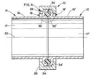
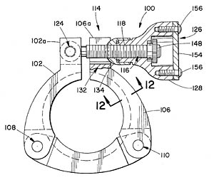
The sealing mechanism is essentially a specialized O-ring that fits in a groove formed into the flange end of the pipe. Opposing flange grooves hold the ring seal, and when compressed together, form the seal, but with no pocket formed along the inner wall of the pipe. It should be noted that this is something of a simplification, since the patent goes into a bit of detail on the size ratios of the groove and the ring seal to form the proper sealing, given the elastometric nature of the seal material. For example, the width of the seal ring is preferably at least two hundredths of an inch (0.020") wider up to as much as five hundredths of an inch (0.050") wider than the total width (W) of the assembled recesses. Additionally, the total radial width of the main body is preferably only slightly less than the average radial width of the recess. While interesting to a design engineer, the important thing in the field is that the necessary compliance of the ring material has already been accounted for.The clamping ring for the pipe joint has also been newly designed. This clamp ring assembly is designed to manually apply the necessary axial clamping loads to the flange assembly and to allow rapid makeup and disassembly of the fitting. Additionally, the clamp ring is arranged so as to allow the assembler to have a proper manual feel when the clamping of the flange fitting is taking place. The assembly is also arranged to eliminate galling of mating metal components and to provide containment of any bearing materials and the like which could contaminate the surrounding environment. The clamping ring utilizes a sort of wedge-shaped internal groove and mates with an opposing external wedge on the flange of the pipe to draw the ends of the pipe together and form the seal against the ring seal.
The utilization of a three-segment clamping ring allows for a more uniform and complete clamp force on the pipe joint, which should result in a better seal with fewer possibilities of surface imperfections or pockets on the innermost part of the seal forming the internal wall of the pipe. It would seem reasonable that the field installation of this mechanism will be less labor intensive than prior technologies, reducing the overall costs of processing piping systems. The reduction in costs associated with easier purging of process piping lines will vary of course, but over time, it may prove to be a substantial cost saver.