
Issue: 9/01
"Striking a balance" is a common phrase that is often used to describe the balancing act between career and family or work and play. It's a comfort level that people seek that brings balance to a hectic lifestyle. This symbolism holds true as Mother Nature's unpredictable weather conditions force one to adjust the temperature setting between air conditioning and heat, trying to find the perfect indoor climate.
Why Balance?
The benefits of balancing a heating or chilled water system and domestic hot water have been well understood for years. According to the ASHRAE Handbook, balance is defined as "to proportion flows within the distribution system (sub-mains, branches, and terminals) according to specified design flow rates." The results of a balanced system equate to improved comfort (a basic necessity), equipment efficiency, energy conservation and cost savings.A correctly functioning hydronic heating and cooling system provides a comfortable indoor climate and enough domestic hot water so the building occupants can carry out their daily tasks. The owner has the satisfaction of knowing that his building has been proven through the balancing of the mechanical and plumbing systems to perform the way the design consultant intended. If the balancing valves are not correctly sized, then the size of the pumps and piping must be increased to force the flow to all parts of the building. This will require more power consumption than necessary. A crucial part of the design is the provision of adequate plant to meet the needs of the building; however, it is equally important to ensure that the power developed by the plant reaches every part of the building in the design flow rates required for heating or cooling.
A handy point of reference can be found in the ASHRAE Handbook for Principle and Procedures for Balancing Hydronic Systems. It states: "Both air and water-side balance techniques must be performed with sufficient accuracy to ensure that the system operates economically, with minimum energy, and with proper distribution. Air-side balance requires a precise flow measuring technique, because air, which is usually the prime heating or cooling transport medium, is more difficult to measure in the field. Reducing the airflow to less than the design requirement directly reduces the heat transfer. In contrast, the rate of heat transfer for the water side of the terminal does not vary linearly with the water flow rate. Therefore, the proper balancing valve with the correct control characteristics must be provided at each terminal to proportionally balance the water flow rate according to the design conditions."
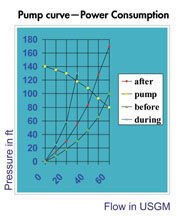
A balanced water system provides considerable energy savings. Before any balancing takes place, the pump is moving more water than required by the system over a short distance because water will always take the path of least resistance. The regulating of the circuit balancing valves reduces the volume of water being circulated and drives the system curve up the pump curve, pushing adequate flow to all branches of the system. The pump curve in Chart A illustrates how power consumption is affected. The lower the pressure, the higher the volume created. The higher volume, the more power used. The system curve climbs the pump curve when control valves close. The net effect of reducing flow is a reduction in power consumed. Remember: if the volume drops by half, the power consumed drops by an eighth!
To further illustrate this point, refer to the principle of "Water Balance by Proportional Method," as published in the ASHRAE Handbook. "The proportional method of water side balance uses as-built conditions and adapts well to design diversity factors. Circuits in a system are proportionally balanced to each other by a flow quotient, which is actual flow rate divided by the design flow rate through the circuit."
Flow quotient = Actual flow rate divided by Design flow rate

A Balancing Act
The importance of specifying the correct circuit balancing valve has a major influence on pump size, balancing ease and overall system performance. To that end, circuit balancing valves must perform two functions: balancing and isolation.First, the main function of a balancing valve is to control flow throughout the system, but not add unreasonable head to the total system resistance. The globe-style valve, with a parabolic-shaped disc that requires multiple turns of the handwheel, has a larger bore and therefore a higher Cv. The larger bore minimizes pump head loss, while the parabolic disk allows for fine regulation, more control and the introduction of small to large head loss throughout the system. On the other hand, ball-style circuit balancing valves must have a reduced bore in order to have any influence on reducing flow in the system. The dramatic reduction in bore size on each valve eventually leads to a system requiring larger pumps than necessary. Larger pumps mean higher capital costs and increased running costs. It follows that smaller pumps mean smaller capital costs and reduced running costs.
With regard to "Water-Side Balancing" function, the ASHRAE Handbook states, "The water side should be balanced by direct flow measurement. This approach is accurate because it avoids the compounding errors introduced by temperature difference procedures. Measuring the flow at each terminal enables proportional balancing and ultimate matching of the pump to the actual system requirements (by trimming the pump impeller or reducing the pump motor power, for example). In many cases, reduction in pump operating cost will pay for the cost of water side balancing." In simpler terms: Smaller pumps lead to reduced capital costs and lower running costs.
The second function of a balancing valve is to provide tight shut off when plant or branch (circuit) isolation is required. Globe-style and ball-style circuit balancing valves both offer positive shut off.
As depicted in Chart B, Balancing Valve Flow Characteristics, the globe-style valve has a more linear flow curve than the ball-style valve. The ball valve flow is controlled over only a 90-degree turn of the handle. A 15-degree handle movement will affect the flow measurement range by as much as 30%. In order to affect the same 30% change in flow measurement, the globe-style valve would require at least a 502-degree handle position change. In essence, the multi-turn valve allows for greater control with more turns of the handle vs. a ball-style with a 90-degree turn. Multiple turns result in better control and improved signal accuracy.
One should also consider what happens to flow in a ball valve as it is closed. Imagine the aperture, or flow path for the water, in a regulated ball-style balancing valve. A crescent shape is formed between the ball and the seat at entry and exit, which is offset to the main flow axis of the valve, causing a localized velocity increase. Compare this to the seat in a globe valve, which controls regulation with a specially profiled disc. This design creates uniform flow velocity over the full seat circumference and the body seating area, and is not an obstruction in the direct flow path.
In addition to the specially profiled disc, a multi-turn circuit balancing valve has a micrometer-type operation of the handwheel, giving easy adjustment and fine setting to accurately carry out the proportional balance. Compare that to the imprecise positioning of the lever handle on a ball valve.

Getting Down to Basics
The concept of proportional balancing is dependent on two basic principles:1. The adjustment of a circuit balancing valve in a sub-circuit alters the flow, not only in the sub-circuit, but also in the other circuits within the system. If such an adjustment reduces the flow in the sub-circuit, then the flow elsewhere must increase, as the total mass flow rate is constant.
2. If water flows through a pipe that has a number of branches, then the percentage of the total flow in each branch remains constant irrespective of how the total mass flow changes.
An example of proportional balance and the effects can be seen in Chart C, Proportionally Balanced Branch with Sub-Circuits.
The balancing of the water system is totally dependent on how accurately the valves and piping are sized at the design stage. If the balancing valves are incorrectly sized, i.e. always installed at pipe size, the balancing engineer will notice inconsistencies during his initial scan for flow in each branch. The engineer will find many of the least favored valves will not have sufficient flow rate to give an adequate pressure drop signal to determine the index circuit or circuit with least amount of flow.
The proportional balance can only be carried out in the most favored circuits, with the hope that eventually the flow will increase enough to get some sort of reading from the oversized valves. The solution is to size balancing valves that give a flow signal when fully open greater than 0.4-ft. but less than 3-ft. head. This procedure gives a chance of obtaining a reading in the index circuits and does not add excessive head to the pump. Balancing valves installed in the bypass pipe of a three-port Temperature Control valve should ideally be sized for operation around the 50% open position.
To Balance or Not to Balance?
Of course, there is only one correct answer. A balanced system provides the following benefits:
- A comfortable indoor climate
- Sufficient domestic hot water to all parts of the building
- Correct flow in boilers and chillers
- Desired flow distribution throughout the building
- Energy savings and cost savings
- Trouble-free operation and ease of maintenance
- Lower capital costs
In summary, whether a system is designed for heating, cooling or water distribution, it must be properly adjusted and balanced for optimum performance. Valuable time and money can be saved when the system being installed matches a pre-determined design, and accurate pressure-drop calculations have already been made.
Quotations from the ASHRAE Handbook are reprinted by permission from ASHRAE 1991 Handbook-HVAC Applications. Copyright 1991, American Society of Heating, Refrigerating and Air-Conditioning Engineers, Inc. www.ashrae.org.

