
Our firm designs hydronic heating systems for custom residential and light commercial buildings. Many of the homes have floor areas of 10,000 square feet or more. They include loads such as high-capacity water heating, driveway snowmelting, and pool heating; these are in addition to space heating loads. Such projects quickly push boiler capacity into the several hundred thousand Btu/hr range, and blur the traditional distinction between “residential” and “commercial” system design.
Our non-residential projects include municipal buildings, large garage facilities, churches, fire stations, and manufacturing facilities. The vast majority of these buildings are slab-on-grade and well suited to floor heating. The design heating loads of these structures are often several hundred thousand to one million Btu/hr.
There are currently hundreds of options for providing this level of heat input to a system. They include a single boiler or multiple boiler system fired by gas, oil, wood/wood pellets or electricity, as well as non-combustion options such as a geothermal heat pump. Of these, gas- and oil-fired boilers are still the most common.
So, what does a boiler plant capable of 1,000,000 Btu/hr output look like? This month we’ll look at traditional and contemporary offerings for producing this level of heat output. These “solutions” are well suited for large residential systems with high demand loads (six or more bathrooms and/or full driveway snowmelting). They also are ideal for commercial buildings, especially those using lower-temperature distribution systems.
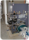
Figure 1.
Single Boiler Solutions
Prior to 30 years ago, many hydronic systems for larger buildings used a single large boiler such as the one shown inFigure 1. This is a section cast iron boiler that’s assembled on site. A boiler of this design with an IBR-rated output of about 1,000,000 Btu/hr and equipped with a dual fuel (gas or oil) burner is 39 inches wide, 61 inches tall, and 79 inches long (including the burner). It weighs about 3,500 pounds (empty) and holds 132 gallons of water.Its manufacturer recommends a rear clearance of 36 inches and side clearance of 39 inches when a tankless coil heat exchanger is installed. A boiler this size is typically mounted on a slab-on-grade floor and vented to a chimney.
Sectional cast-iron boilers like this have been the workhorses of the commercial hydronics industry for decades. When properly applied and serviced, they can last upwards of 30 years. The large metal and water volume of such boilers provides thermal stability to help prevent short-cycling. Section cast-iron boilers also have low head loss, which usually allows all system flow to pass through the boiler. This eliminates the need for a separate boiler circulator, reducing both installation and operating costs.
The combination of high thermal mass and low head loss lets these boilers operate at higher temperature differential (40°F or more in some cases). This allows for reduced flow rate without damaging the heat exchanger. When properly sized and maintained, these boilers can operate in the low- to mid-80% seasonal efficiency range.
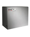
Figure 2. Courtesy of Aerco
Some boilers in this category use a single heat exchanger assembly made of stainless steel or aluminum to withstand the acidic condensation. Others use a primary heat exchanger made of finned copper tubing in combination with a stainless steel secondary heat exchanger. The copper heat exchanger operates above the dewpoint of the exhaust gases.
After passing through the primary heat exchanger, the exhaust gases are further cooled and condensed within the secondary heat exchanger. At least one manufacturer offers a condensing-capable boiler with a cast-iron heat exchanger. The downward flow of combustion products in this boiler sweeps most condensate off the cast-iron sections to minimize corrosion. The predicted life expectancy is several decades. Examples of boilers with the above features are shown inFigures 2, 3, 4and5.
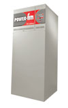
Figure 3.Courtesy of Lochnivar
Product Details for Figures 2-5
Figure 2.Courtesy of Aerco
Model: MLX-1060
Footprint = 27 inches x 49 inches
Dry weight = 761 lb
Water Content = 8.2 gallons
Maximum output = 975,000 Btu/hr
Modulation (Turn down ratio) = 23:1
Heat exchanger: Cast aluminum
Figure 3.
Courtesy of Lochinvar
Model: PBN1302
Footprint = 28.5 inches x 23.25 inches
Dry weight= 718 lb
Water Content = 5 gallons
Maximum output = 1,105,000 Btu/hr
Modulation (Turn down ratio) = 5:1
Heat Exchanger: Finned copper tube
Figure 4.
Courtesy of Viessmann Manufacturing
Model: Vitocrossal 300
Footprint = 40 inches x 70.5 inches
Dry weight = 1202 lb
Water Content = 87.2 gallons
Maximum output = 1,030,000 Btu/hr
Modulation (Turn down ratio) = 5:1
Heat Exchanger: Stainless Steel
Figure 5.
Courtesy of HydroTherm
Model: KN10
Footprint = 29.5 inches x 43.5 inches
Dry weight= 1100 lb
Water Content = 14 gallons
Maximum output = 880,000 Btu/hr
Modulation (Turn down ratio) = 5:1
Heat Exchanger: Cast-iron
(downward combustion flow)
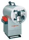
Figure 4.
Courtesy of Viessmann Manufacturing
Divide and Conquer
Multiple boiler systems have been gaining ground in commercial hydronic systems over the last two decades. A survey on boiler preferences conducted by PM Engineer in 2001 indicated that multiple boiler solutions are considered by 37% of the respondents when the design load is between 150,000 and 250,000 Btu/hr. When the design load hits 300,000 Btu/hr or higher, another 43% of respondents stated they considered multiple boilers.The reasons cited for use of multiple boiler systems are not surprising. Fifty-six percent of the respondents liked the fact that multiple boiler systems provide partial heat delivery when one of the individual boilers is not operating. Forty percent also recognize the higher seasonal efficiency provided by multiple boiler systems.
When this survey was conducted, the majority of multiple boiler systems used on/off boilers. Since that time, the availability of small mod/con boilers has increased significantly. Many of these boilers are now being used to build multiple mod/con boiler systems that provide the following advantages:
• The system turndown ratio equals the boiler turndown ratio times the number of boilers in the system. For example, when four boilers with a rated capacity of 250,000 Btu/hr each and a turndown ratio of 5:1 are combined, the turndown ratio of that multiple boiler system is 20:1, as shown inFigure 6. A high turndown ratio allows the system to closely track the heat load and minimizes the potential for short-cycling.
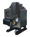
Figure 5.
Courtesy of HydroTherm
• Smaller/lighter boilers are easier to transport and can often be wall mounted to conserve floor space in mechanical rooms.
• Repair parts for smaller boilers are more readily available because these boilers are used in both residential and commercial applications.
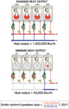
Figure 6.
Piping Pointers
Several piping details are important when two or more mod/con boilers are combined into a multiple boiler system:• Each boiler should have its own circulator and check valve. Flow should only pass through a boiler when that boiler is firing, and perhaps for a short post-purge cycle. Doing otherwise uses the inactive boiler as a heat dissipator.
• Circulators should push flow into the boiler rather than pull flow from the boiler. This detail causes a rise in pressure within operating boilers and helps prevent steam flashing when the boiler operates at elevated temperatures. This is especially important in boilers with compact/low-water content heat exchangers.
• The multiple boiler system should be hydraulically isolated from the distribution system. This can be done using closely spaced tees or a hydraulic separator, as shown inFigure 7. The hydraulic separator, if used, also provides air separation and dirt separation for the system. Hydraulic separation by either means prevents interference between the boiler circulators and the system circulator(s). It also ensures proper flow through the boilers regardless of zone flow rates in the distribution system.
The staging and modulation of the boilers in these schematics is controlled based on system supply temperature measured on the outlet side of the point of hydraulic separation. This accounts for any mixing taking place within the closely spaced tees or hydraulic separator, and allows the boiler system to operate at the lowest water temperature commensurate with the current heating load. The lower the boiler temperature, the higher its efficiency.
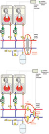
Figure 7.
Walls, Stacks and Racks
Small mod/con boilers lend themselves to a variety of mounting options. One of those options is wall mounting.Wall mounting conserves floor space in a mechanical room and usually allows for short venting runs when the boilers are mounted on an external wall. However, when considering external wall mounting, be sure the exterior of the wall is suitable for venting with regard to clearances to windows and doors.
Also remember that these boilers can create visible plumes of water vapor from their vent terminals during cold weather. These plumes can create aesthetic issues with owners, especially if the vents face the front of the building. Finally, be sure the exhaust plumes are directed sufficiently away from the building to prevent frost formation on the sides or overhangs of the building during cold weather.
Some higher capacity mod/con boilers also can be stack mounted. In this case, the boilers have internal structural frames to support the weight of the upper boiler.
Another novel mounting system places multiple boilers back-to-back above a pre-engineered header/hydraulic separator assembly, as shown inFigure 8.
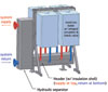
Figure 8. Courtesy
of Sinus North America
This arrangement allows for a relatively compact footprint, full serviceability and all the piping details previously discussed.
The physical package that constitutes a 1,000,000 Btu/hr boiler has certainly changed over the last few years. The trend is toward smaller footprints, wide-range modulation and the ability to operate with sustained flue gas condensation when combined with lower temperature loads.
In the future, look for such boilers to offer more options for interfacing with building automation systems, as well as Web-enabled internal controls for monitoring and adjustment. Also look for increasingly sophisticated combustion controls that provide even wider modulation ranges and “self-tune” for changes in fuel make-up or venting resistance.
In closing, remember that the boiler, no matter how well designed, is only part of the system. A well-designed system is greater than the sum of its parts.
