An ideal heating system would continually and instantaneously adjust its rate of heat delivery to match the heat loss of the building it serves. The indoor air temperature would remain rock stable. There would be no difference in comfort regardless of outside conditions.
No hydronic heating systems can claim to meet this ideal. Instead interior air temperatures cycle up and down (albeit less than with most forced air systems) as heat is delivered in "spurts" rather than as a smooth continuous process. This is the result of water being supplied to the system's heat emitters at the same (design) temperature regardless of the current heating load. The amount of heat delivered to the building is regulated by starting and stopping flow through the heat emitters. It's like driving a car by repeatedly alternating between full throttle and coasting. It'll get you there, but the ride is not as smooth as it could be.
Outdoor reset control was developed to improve upon this method of heat delivery to enable heat to flow from the heat emitters to the space being heated smoothly, continuously, and at just the right rate.
All outdoor reset controls use outside air temperature as the basis for determining an ideal "target" water temperature to be supplied to the system's heat emitters. The goal is always the same: To maintain the rate of heat delivery from the heat emitters equal to the rate of heat loss from the building. In short, it's like adding cruise control to the heating system.
Benefits Galore
Before getting into the technical details of how outdoor reset control works, let's consider the many benefits it offers. Here's a summary:
- Less fluctuation of indoor temperature: When the reset control is properly adjusted, water temperature is perfectly matched to load conditions at all times. There's minimal chance of room temperature overshoot (other than from internal gains, which we'll discuss later). Excess heat is not being forced into the thermal mass of either the heating system or the building by "overheated" water. Rooms don't undergo noticeable changes in temperature, as is often the case when heat is delivered through on/off cycles.
- Reduced expansion noises: With reset control, changes in water temperature take place over hours-even days-rather than in seconds, as it can when on/off flow control is used. Piping expansion noises are far less likely to be noticed. The thermal expansion movement of materials such as flooring and framing-often part of radiant panel systems-is also reduced. Most owners perceive a quiet system as a quality system.
- Reduced possibility of thermal shock: This applies to the heat source, the distribution system, and even building materials (in the case of radiant panel heating). Hot boilers are less likely to receive slugs of cold water from zones that have not been flowing for several hours. Wood flooring used in conjunction with radiant floor heating is less prone to cupping or cracking when undergoing gradual temperature changes.
- Nearly constant water circulation: Because the water temperature is "just right" for the prevailing conditions, flow through the heat emitters is seldom interrupted. Constant circulation helps even out heat delivery to different parts of a building that may contain localized heat sinks. The area just inside a large overhead door of a garage equipped with floor heating is a good example. Constant circulation can move heat stored within the interior slab areas to the area(s) of higher loss. Besides improving comfort, constant circulation protects against localized freezing during deep setbacks or boiler down time.
- Reduced fuel usage: Outdoor reset control has demonstrated its ability to reduce fuel consumption in both residential and commercial buildings. The exact savings obviously vary from one project to another. Conservative estimates of 10 to 15% are often cited.
The Mathematics of Reset Control
The classic model used to estimate building heat loss states that the rate of heat loss is proportional to the difference between the inside and outside air temperature. The constant of proportionality is determined by the size of the building as well as the materials used to construct its thermal envelope. This relationship can be represented as follows:Equation 1
Qbldg loss = (UA)bldg x (Tinside air - Toutside air)
where:
UAbldg = the overall heat loss coefficient of the building (Btu/hr/deg. F)
Tinside = inside air temperature (in deg. F)
Toutside = outside air temperature (in deg. F)
The (UA) constant is the end result of heat loss calculations. If the building's design heat loss is known, along with the corresponding gT between inside and outside air temperature, (UA) can be determined by dividing the former by the latter. For example: If a building has a design heat loss of 65,000 Btu/hr when maintained at 70 deg. F, while the outside temperature is 0 deg. F, the value of UA is:
(UA)bldg = 65000/(70 - 0) = 929 Btu/hr/deg. F
Another "simplified" model can be written to describe the heat output of a hydronic heat emitter. It states that the rate of heat output is proportional to the difference between the building's inside air temperature and the water temperature supplied to the terminal unit. Mathematically, this yields:
Equation 2
Qoutput = k x (Twater - Tinside air)
The constant k depends on the type of heat emitter used. It's found by dividing the required (design) heat output of the heat emitter by the difference between the supply water temperature and the inside air temperature at design conditions. For example: If a radiant floor must deliver 65,000 Btu/hr to a building that's to be maintained at 70 deg. F using water supplied at 110 deg. F, the value of the constant K would be:
k = 65000/(110 - 70) = 1625 Btu/hr/deg. F
If the inside air temperature is to remain constant, the rate of heat output must match the rate of heat loss. If we set Equations 1 and 2 equal to each other and simplify, we get:
Equation 3
Twater = Tinside air + [(UA)bldg/k] x (Tinside air - Toutside air)
The terms in the square brackets are constants for a given building equipped with a given heat emitter system. Hence, they can be reduced to a single constant. That constant determines the necessary rise in water temperature per deg. F drop in outside air temperature and is called the "reset ratio" for the system.
If we insert the numbers from the above examples into Equation 3 we get:
Equation 4
Twater = 70 + [0.571] x (70 - Toutside air)
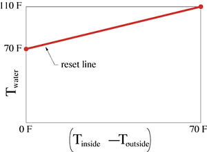
In words, this equation states that the water temperature supplied to the heat emitter should start at 70 deg. F and increase by 0.571 deg. F for each deg. F the outside air temperature drops below 70 deg. F. For example: When it's 32 deg. F outside, the water should be supplied to the radiant floor circuits at:
Twater = 70 + [0.571] x (70 - 32) = 91 deg. F
Those who remember their algebra recognize Equation 4 as that of a straight line with a slope of 0.571 and a vertical intercept of 70. A graph of this reset line is given in Figure 1.
The higher the design water temperature of the heat emitter system, the steeper the slope (reset ratio) of its reset line.
Complicating Factors
Based on the above models for building heat loss and heat emitter performance, it would appear possible to maintain a constant indoor air temperature using a control that only monitors outside air temperature (provided its reset ratio was set properly). Unfortunately, there are several conditions that influence building heat loss that are not accounted for in these simple models. For example, a change in wind speed or direction may significantly effect a building's heat loss, but it is not compensated for in Equation 3. Internal heat gains from sunlight, occupants and equipment can also reduce the heat required from the heat emitters, even on very cold days, but again would not be compensated for by a control that only "sees" outside air temperature as its input variable.Although buildings with very low internal heat gains can be controlled based on reset controls that react solely to outside air temperature, they are the exception rather than the norm. In most buildings, reset controllers need some type of interior air temperature feedback to judge how they are doing. Without this feedback, the reset control is "running blind" to interior temperature and cannot compensate for internal gains, wind effects or any other factors (other than outside temperature) that increase or decrease the output required of the heat emitters. Uncomfortable conditions are almost sure to result.
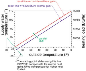
Indoor temperature feedback may be provided through a simple on/off thermostat that temporarily prevents further heat input from the device the reset controller regulates (boiler, mixing valve, etc). It can also be provided by an interior temperature sensor that allows the reset control to automatically shift its reset line downward (to compensate for internal heat gain) or upward (to compensate for a higher than normal heat loss).
An example of such a "parallel shift" is shown in Figure 2. Note that the reset line maintains the same slope (reset ratio), but its starting point slides along the green starting point line.
Theoretically, the starting temperature necessary to compensate for an internal heat gain can be calculated using Equation 5:
Equation 5
Tstarting = Tinside air - R x Qgain/(UA)bldg x (1 + R)
where:
Tinside air = desired inside air temperature (deg. F)
R = reset ratio of the system
Qgain = rate of internal heat gain (Btu/hr)
(UA)bldg = overall building heat loss coefficient (Btu/hr/deg. F)
The starting temperature can also be adjusted upward to compensate for higher than normal heat losses. Just treat the higher loss as a negative heat gain in Equation 5.
When a Line Is NOT a Line
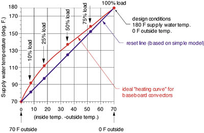
The simple proportional model used to predict the heat output of a hydronic heat emitter (Equation 2) doesn't account for the nonlinear characteristics of convective and radiative heat transfer. If these effects are to be factored in, the reset line must change into a curve. That curve passes through the same starting point and design load point as the reset line, and is slightly humped up in between. Heat emitters with higher proportions of convective heat output tend to have more pronounced curvature in their theoretically ideal heating curves.The curve shown in Figure 3 plots the water temperature required by a typical baseboard convector as a function of outdoor temperature. The points plotted along the curve represent 100, 75, 50, 25, and 10% of design load.
If the water temperature supplied to the baseboard system tracked along the blue reset line, and the building heat loss was directly proportional to the delta-T between inside and outside air temperature, the inside air temperature would droop slightly during part load conditions (because the output of the baseboard would be less than the heating load). However, if the water temperature tracks along the red heating curve, the heat output from the baseboard should precisely match building heat loss under all load conditions.
This heating curve versus reset line scenario is handled differently by different controllers/systems. On systems using indoor thermostats, the reset ratio (slope of the reset line) can be set slightly higher than necessary with reliance on the thermostat to interrupt heat input when necessary to prevent overheating. In other cases, the heating line can be parallel-shifted upward while retaining its original reset ratio. The latter approach usually results in good load tracking over the upper half of the load range but produces higher than necessary water temperatures during low load conditions. Again, a room thermostat must occasionally interrupt flow to the heat emitters to prevent overheating in mild weather.
Some reset controls can be equipped with indoor temperature sensors rather than thermostats. Their control algorithms, in combination with continuous feedback from the indoor sensor, allow the control to automatically (and continuously) shift the starting point of the reset line up or down as necessary to match the heat output from the heat emitters to the load. In effect, the reset line is shifted until it intersects the implicit heating curve of the heat emitter system at all load conditions.
Still another method uses the capability of a microprocessor to mathematically synthesize the heating curve based on the type of heat emitter used, along with the starting point and design load conditions. Water temperature is then calculated based on this heating curve instead of the reset line.
Although these methods vary in mathematical sophistication, all have proven their ability to provide very acceptable interior comfort. All will improve comfort and reduce energy usage relative to a system using on/off flow control and constant water temperature.
Methods of Implementing Reset Control
There are two fundamental methods of implementing reset control in a hydronic system. Each can be used by itself, or the two can be used in combination. They are:1. Boiler Reset
2. Mixing Reset
A boiler reset control takes over operation of the burner from the standard (fixed) high limit control. As the outside air temperature changes, the reset control continually recalculates how high the boiler water temperature will be allowed to climb and operates the burner accordingly.
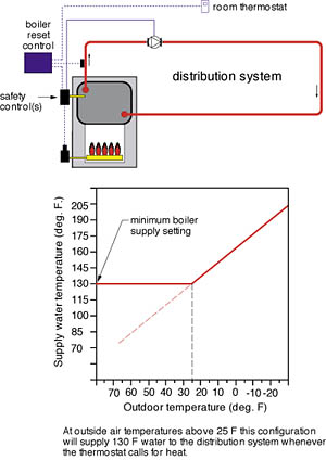
This method is well suited for systems using relatively high temperature hydronic heat emitters, like baseboard and panel radiators. However, because conventional boilers should not operate at temperatures below the dewpoint of their exhaust gases, boiler reset is somewhat limited when used in conjunction with low temperature heat emitters. In such cases, boiler water temperature is "partially reset" down to a user-selected minimum temperature setting, as shown in Figure 4. For the case depicted, the boiler outlet temperature would not be reset below a nominal 130 deg. F. In this case, the minimum water temperature happens to corresponds to an outside air temperature of 25 deg. F. Air temperatures of 25 deg. F and higher represent a large percentage of the heating season in many parts of the U.S. Because the nominal 130 deg. F water temperature supplied to the heat emitters may be higher than necessary during much of the heating season, a room thermostat must be used to cycle the circulator or zone valve on and off to prevent overheating.
Most multiple boiler system controls also provide boiler reset. They monitor the temperature of supply water in the common header piping and vary the firing cycles of the boilers as necessary to keep it close to the calculated target value.
Most boiler reset controls are NOT recognized as safety devices. They do not take the place of a manual reset high limit control often required by codes. When a boiler reset control is used, these high limit devices should be set high enough so as not to interfere with the reset operation. Under most conditions, the boiler reset control handles boiler firing, but the high limit control(s) remain in place as safety device(s) should the reset control fail to limit boiler temperature.
When the system includes loads supplied through heat exchangers, such as indirect domestic water heating, snowmelting or pool heating, the control system is normally configured to "ignore" the boiler reset routine during a call from one or more of these loads. Instead boiler water temperature is allowed to climb to its upper limit setting (typically 180 to 200 deg. F) to maximize energy flow through the heat exchangers. Many boiler reset controls have this "bypass logic" already incorporated in their control algorithms.
Mixing reset requires a mixing device between the boiler loop and a separate distribution circuit. This device could be a modulating 2-way, 3-way or 4-way valve, or a variable speed injection pump. It provides the proper supply water temperature to the distribution system. It also acts as a "clutcV'when necessary to prevent the cold thermal mass of the distribution system from extracting heat faster than the boiler can produce it. This latter function, commonly called "boiler protection," is crucially important when a conventional boiler provides heat to a slab-type floor heating system.
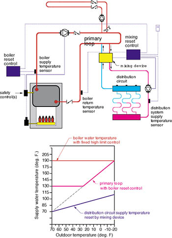
Boiler reset can be used in combination with one or more mixing reset controls in the same system. The boiler reset control monitors and adjusts the water temperature in the primary loop by varying the firing cycles of the boiler(s).
Typically the primary loop temperature is partially reset as discussed earlier to prevent the boiler(s) from operating below dewpoint temperature. The n-fixing reset controls operate their respective mixing devices to reduce the primary loop water temperature as appropriate for the loads they serve. An example of such a system is shown in Figure 5.
Combining boiler reset and mixing reset yields the following benefits:
- Increased boiler efficiency due to lower stack and jacket losses.
- Improve comfort, since all heat emitters-whether piped directly off the primary loop or through a mixing device-undergo less on/off cycling under part load conditions.
- Increased rangeability of mixing devices under part load conditions (improved control loop stability).
- Reduced heat loss from primary loop piping.
Reset control can be adapted to almost any hydronic system. It's an elegant means of control that truly helps bring out the qualities hydronic heating is known for. Try it once and you'll be convinced.
