Do you remember when you were introduced to PEX tubing? For me, it was 1982. I was sitting in the office of a local manufacturer’s rep. He handed me a short piece of what appeared to be thick garden hose. I looked it over, bent it back and forth a few times and handed it back to him, unconvinced it had any merit over my staple piping material - copper tubing.
However, his passion for the product eventually convinced me to try it in a new radiant floor heating project. Needless to say, the rest is history. That project and hundreds more have proven that PEX, as well as its derivatives such as PEX-AL-PEX, are reliable performers in radiant panel heating applications.
Which brings us to distribution systems. Traditionally, most were designed around rigid metal piping, but such “topologies” don’t necessarily take advantage of PEX or PEX-AL-PEX tubing. The link to widespread usage of PEX and PEX-AL-PEX tubing is a manifold system that interfaces it to rigid piping and facilitates the advantages of parallel distribution circuits.
Today, North American engineers have a wide range of manifold hardware to choose from. These products range from simple “valveless” headers to manifolds with integral balancing valves, flow meters and even electronic controllers. Larger floor-mounted manifold systems allow for efficient and fast placement of equipment in mechanical rooms. This article provides an overview of what’s available across the spectrum of modern manifold systems.
Valveless
The simplest manifolds are formed from copper tubing using T-drills® and swagging. An example is shown inFigure 1.Such manifolds are ideal for radiant panel circuits in situations where circuit-by-circuit balancing is not required. An example would be a large open-plan garage where several tubing circuits of approximately equal length are embedded in the slab. Since such areas are typically controlled as a single zone, and the circuits are essentially self-balancing, it’s fine to simply divide up the flow into equal portions for each circuit.
Manufacturers of PEX and PEX-AL-PEX tubing offer adapter fittings that can be soldered to the side ports of copper manifolds. Another option is to equip each manifold connection with an isolation valve. I strongly recommend this option for commercial or industrial floor heating. It allows any given circuit to be isolated from both supply and return manifolds if that circuit is ever damaged due to building modifications. Ball valves with integral adapters to PEX or PEX-AL-PEX tubing are ideal for such projects. Such valves also make it easier to fill and purge larger manifold stations by routing purging flow through one circuit at a time.
Notice that the manifold station has been configured for reverse return piping. Although most manifold stations of six circuits or less do not require this detail, it does help balance flow rates in long commercial manifold stations. Also notice that purging valves have been included at the end of both supply and return manifolds. Flexible polyethylene sleeving protects the tubing at floor level.
Twist To Tweak
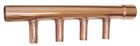
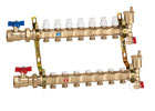
There are many manifold systems available with integral valves. Typically, they are constructed of brass or stainless steel. Some manufacturers provide segments with two, three or four connections that can be linked together to construct larger assemblies. Others provide single segment manifolds equipped for two to 12 circuits. An example of the latter is shown inFigure 3.Valved manifolds allow the flow rate of each circuit to be adjusted. This process is referred to as balancing. The goal is to provide the proper heat output from each circuit.
Proper balancing requires a known relationship between the thermal output of the heat emitter as a function of the flow rate through it. The required design load heat output thus has an associated flow rate. This flow rate can be established through direct readings on a flow meter or by determining the necessary pressure drop across the balancing valve that will allow this flow to develop.
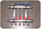
The easier of these two methods is direct measurement of the circuit flow rate. Several manifold manufacturers provide options to this end. One is shown in Figure 4, where a spring-loaded flow meter is an integral part of the manifold assembly.

Manifolds are typically sized so flow velocity from the supply main does not exceed four feet per second. This minimizes noise and makes the pressure drop along the manifold very small relative to the pressure drop across individual circuits. Most residential systems can use 1-inch or 1.25-inch (pipe size) manifolds. Larger manifold stations found in commercial and industrial radiant panel systems are typically 1.5- or 2-inch pipe size.
Beyond Radiant Panels
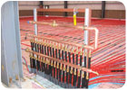
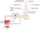
Most North American mechanical professionals think manifolds are solely for radiant panel heating systems. Although the majority are used for such systems, limiting the scope of their usage to such systems is to overlook some excellent opportunities.One of those opportunities is known as a homerun distribution system. An example of such a system supplying individual finned-tube baseboards is shown in Figure 6.
Manifold-based homerun distribution systems also are excellent for panel radiator systems, or even a combination of heat emitters. They are especially well-suited for retrofit applications where the small flexible tubing can be pulled through framing cavities much like electrical cable.
Manifolds Plus
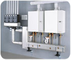
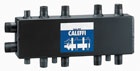
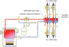
Beyond the “smaller” manifolds used in radiant panel and homerun distribution systems are larger manifold stations for use in mechanical rooms.An example of one such product is shown in Figure 7a and Figure 7b. This device combines stacked manifold chambers with a hydraulic separation chamber on the left side. Two closely spaced holes in a vertical baffle plate connect the manifold chambers with the hydraulic separation chamber. This geometry effectively isolates the pressure dynamics of the boiler circulator from those of the distribution circulators.
A larger version of this same concept is shown in Figure 8. Here, a horizontal floor-mounted steel assembly forms both supply and return manifolds. Multiple boilers, each with its own internal circulator, connect to the manifold. A hydraulic separation chamber connects to the manifold assembly at the left end and forms the interface to the distribution system.
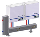
Each boiler is equipped with an internal circulator and check valve. They each connect to the horizontal steel manifold through flexible stainless steel lines sets. The horizontal manifold connects to a vertical hydraulic separation chamber at the left end. This, in turn, supplies another horizontal manifold, which serves three independent distribution pumping modules. Notice that all components are well insulated to minimize heat loss to the mechanical room, an important detail considering the surface area of these assemblies.