
Variable-speed injection has been used in North American hydronic systems for well over a decade. A basic schematic for this method of water temperature control is shown inFigure 1.
Two important details are crucial to proper operation:
1. The injection risers are connected to the boiler loop and distribution system using a pair of closely spaced tees. This separates the dynamic pressure of the injection pump from that of the boiler loop circulator, as well as the distribution circulator.
2. The set of closely space tees connecting the risers to the boiler loop is at least 18 inches above the tees connecting the risers to the distribution system. This arrangement forms a thermal trap to prevent heat migration into the distribution system when the injection circulator is off.
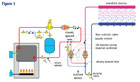
Figure 1
The small wet-rotor circulators typically used for injection mixing are often significantly oversized for the necessary flow and head requirements. This happens because the North American hydronics industry currently doesn’t offer “micropumps” specifically tailored to the minimal flow and head requirements of a typical residential injection mixing system. Thus, it’s common practice to use a standard 1/25-hp zone circulator for the injection pump. Such pumps are readily available and inexpensive.
Low Rangeability
Because the injection pump is often oversized, it’s capable of injecting all the flow needed for design load conditions while operating at a small fraction of full speed. This results in low “rangeability” and limits the injection controller’s ability to fine-tune the water temperature in the distribution system.
To compensate for these effects, a flow restrictor valve is installed in one of the injection risers to throttle away additional head and force the injection pump to operate at higher speeds. When this valve is properly set, the injection pump should run at or close to full speed under design load conditions.
The graphs in Figure 2 show how the system curve for the injection riser piping steepens as the flow restrictor valve is partially closed. When this valve is properly set, the system curve for the injection risers will cross through the full-speed pump curve at the desired (design load) injection flow rate.
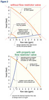
Figure 2
As Easy As 1, 2, 3
The easiest way to set the flow restrictor valve is to have a flow metering device installed in the return injection riser, as shown in Fgure 1. I prefer to use a flow restrictor valve with a built-in flow meter, but the flow meter could also be a separate component from the flow restrictor valve. Be sure the flow restrictor valve is a “globe type” mechanism specifically designed for throttling flow. Do not use a ball valve for this application.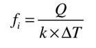
Equation1
Where:
ƒi = required injection flow rate (gpm)
Q = rate of heat transfer to distribution system (Btu/hr)
∆T = temperature difference between supply and return injection risers (°F)
k = a constant depending on fluid used (for water, k = 490; for 30% glycol solution, k = 479; for 50%, glycol solution k = 450)
Here’s an example: A low temperature radiant floor panel has a design output of 50,000 Btu/hr when supplied with 105°F water and operating with a 15°F temperature drop. What is the required injection flow rate of 170°F water through the two-way valve under these conditions?
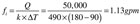
Numbers in Equation 1
Step 2: After the system is filled and purged, operate the injection pump at full speed. Also be sure the flow restrictor valve is fully open.
Step 3: Partially close the flow restrictor valve until the flow rate indicated on the flow meter matches the flow rate calculated in Step 1. Note the position of the flow restrictor valve stem for future reference in case it is moved. You’re done.
The system is now set so that the injection mixing pump will operate at full speed during calculated design load conditions. Provided that the loads and supply water temperatures do not change, the flow restrictor valve should not need further adjustment.
It’s likely that special purpose “micropumps” will eventually be available in North America. These pumps would eliminate the need for “neutering” the performance of an oversized pump to attain the necessary control characteristics. Until that time, use this procedure for maximizing the accuracy of your injection mixing systems.
