
It’s hard to go through a day without hearing or reading about the “greening” of America. This topic often brings to mind methods for harnessing renewable energy sources such as solar collectors and wind turbines. Although these technologies are highly visible, and hence, probably the best-known methods of collecting renewable energy, other approaches hold equal if not better return on investment potential. One of these is a geothermal heat pump system.
Most currently deployed geothermal heat pumps are water-to-air (W/A) units. In the heating mode, they absorb heat from the earth in one of three ways:
1. Ground water is pumped directly through the heat pump(s). This is called an open-loop geothermal heat pump system.
2. Water or a mixture of water and antifreeze is circulated through one or more circuits of high-density polyethylene tubing buried in the ground, and then through the heat pump(s). These are called closed-loop geothermal heat pump systems.
3. Earth heat is directly absorbed into expanding refrigerant contained in closed copper tubing circuits buried in the ground. These are called direct expansion geothermal heat pump systems.
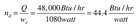
For example, a 4-ton rated (48,000 Btu/hr) W/A heat pump with a PSC-blower motor rated at 1080 watts has a delivery efficiency of (see equation at left):
The hydronic distribution system operates on less than 8% of the wattage of the forced-air system. This is credited to the high specific heat and density of water vs. those of air.
So how does one combine the superior efficiency of a hydronic distribution system with the thermal efficiency of geothermal heat pumps? The simple answer is to replace the refrigerant-to-air heat exchanger in a W/A heat pump with a refrigerant-to-water heat exchanger. The result is a water-to-water (W/W) heat pump capable of delivering heating and cooling via a hydronic distribution system.

Fundamentals
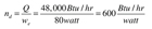
The key to high-performance W/W geothermal heat pump systems is keeping the heating load temperature as low as possible.It’s the same design principle that applies to condensing boilers.The lower the load temperature, the higher the ratio of heat output to electrical input (e.g., the Coefficient Of Performance [C.O.P.]) of the heat pump. See the equation for C.O.P. at left.
Lower load temperatures also increase heat pump capacity.
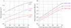
Figure 1
The increased performance of geothermal W/W heat pumps at low load temperatures makes them well suited for use with slab-type floor-heating applications. The ideal situation is a bare concrete slab with tube spacing of 12 inches or less supplying a building with relatively low thermal envelope losses. Such systems may have design water temperature requirements in the range of 100°F to 105°F. Even lower water temperatures as determined by outdoor reset control are possible under partial load conditions.
These same characteristics bode against the use of geothermal heat pumps for supplying higher-temperature hydronic heat emitters such as fin-tube baseboard or unit heaters.
A W/W geothermal heat pump also can produce chilled water for cooling. An internal refrigerant reversing valve, when powered, exchanges the function of the evaporator and condenser. Heat is now extracted from the hydronic load and “dumped” into the earth. The leaving load water temperature in the cooling mode is typically 45°F. This water can be supplied to cooling terminal units such as air handlers, chilled beams or even radiant cooling panels. In all cases, it’s essential to collect and dispose of condensate within the terminal units, and to insulate and vapor seal all piping components to minimize condensate formation.
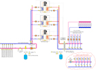
Figure 2
Piping Considerations
There are several characteristics of W/W heat pumps that must be addressed through piping system design. These include:1. Providing proper flow through a heat pump whenever it is operating.
2. Providing a buffer tank in applications where the distribution system has low thermal mass or is extensively zoned.
3. Keeping the entering load water temperature as low as possible.
4. Conserving pumping energy use where possible.
5. Providing hydraulic separation between the heat pump(s), earth loop piping and distribution system.
As is the case with boilers, multiple W/W heat pumps can be used in a staged configuration. In many cases, individual heat pumps can be rack-mounted to minimize the mechanical room footprint. A representative piping schematic using three W/W heat pumps to supply a high thermal mass radiant floor system is shown inFigure 2.
Each W/W heat pump has its own circulator for both the source and load heat exchangers. These circulators operate only when the associated heat pump operates. They are sized for the flow and heat loss requirements of the heat pump, with a small allowance for the head loss of the header piping. The latter is sized for a maximum flow velocity of 2 ft/sec when all circulators are operating. This results in very low head loss along the headers and minimizes interaction between the heat pump circulators. In this example, the earth loop circulator and piping are hydraulically isolated from the headers with a pair of closely spaced tees.

Figure 3
The earth loop manifold piping contains valves for filling and purging. It also should include an air separator, expansion tank and means for adding small quantities of fluid to the earth loop. One option for the latter requirement is an automatically operated fluid makeup unit.
The load circuits also are hydraulically isolated from the heat pump, in this case using a hydraulic separator that also provides air and dirt separation capability. Its presence allows the flow rates through the distribution system to be different than the flow rate through the heat pumps, and like the closely spaced tees, prevents interaction between circulators.
A staging controller, the same as would be used with a multiple boiler system, operates the heat pumps as necessary to maintain the required load supply temperature. This controller can operate using outdoor reset logic and thus allow the water temperature supplied to the load circuits to drop as outdoor temperature increases. The lower the supply temperature, the higher the C.O.P. of the heat pumps.
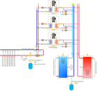
Figure 4
Watch Those Watts
As is true with any hydronic system, increased flow rate yields incrementally higher output from the heat pumps. However, pumping power increases with the cube of flow rate. In many cases, the slight increase in thermal performance achieved by increasing flow is more than counteracted by increased electrical consumption by the circulator(s), as well as the increased installation cost of a larger circulator.Heat pump manufacturers provide thermal performance ratings based on nominal load side flow rates in the range of 1.75-2 gallons per minute per ton (12,000 Btu/hr) of capacity. On the earth loop side, flow rate requirements are higher-nominally about 2.75 gpm/ton of capacity. Flow rates beyond this range will do little other than increase power usage.
Keep in mind that published C.O.P. numbers do not factor in the wattage required to circulate water through either side of a W/W heat pump. To determine thesystemC.O.P., it’s important to include circulator wattage as well as that of the heat pump compressors.
Buffed Up
The vast majority of unitary W/W heat pumps are single-speed devices. Their compressor is either on or off. When on, the distribution system must be able to accept heat at the same rate the heat pump produces it. If this is not the case, the heat pump can short-cycle due to temperature limiting controls, or it could shut itself off based on an internal pressure or temperature protection switch. The latter typically requires manual reset to restart the unit. Both conditions must be avoided.One way to prevent short-cycling and better match heat pump output to a zoned distribution system is through use of an insulated buffer tank, as shown in Figure 3. This tank stores heated water during the heating season. It also can store chilled water during the cooling season.
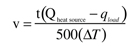
The heat pump is turned on and off based on the temperature of the buffer tank rather than the status of the zone circuits. A setpoint controller or outdoor reset controller monitors tank temperature and cycles the heat pump to maintain it within a preset range. The wider the temperature range and the greater the tank volume, the longer the heat pump cycles will be. The following formula can be used to determine the relationship between cycle length, temperature range and tank volume (see equation at right):
Where:
v = required volume of the buffer tank (gallons)
t = desired duration of the heat source’s “on cycle” (minutes)
Qheat source= heat output rate of the heat source (Btu/hr)
qload = rate of heat extraction from the tank (Btu/hr)
∆T = temperature rise of the tank from when the heat source is turned on to when it is turned off (°F)

Some commercial systems may require simultaneous heating and cooling. In such cases, it’s possible to include two buffer tanks, one for heated water and the other for chilled water. Temperature control logic can be configured to “manage” multiple heat pumps according to the demands of the buffer tanks. Any given heat pump can be operated in either heating or cooling as needed. Representative piping is shown inFigure 4.
Geothermal heat pumps are very attractive for projects requiring both heating and central cooling. Pairing the thermal efficiency of geothermal energy harvesting with the distribution efficiency of hydronic distribution systems makes for a winning combination-one that’s highly scaleable and flexible. This article has presented some basic design principles for such systems. Additional design information on earth loop fields is available from the International Ground Source Heat Pump Association, http://www.igshpa.okstate.edu/.
