
Throughout the history of the American plumbing industry, safeguards have been implemented to ensure the end user has the highest quality water supply. The consumer has come to expect it, but he has rarely thought of the ongoing efforts necessary to make it happen. The 1974 Safe Drinking Water Act, with subsequent revisions, created a tremendous movement in safeguarding this quality by mandating that the ultimate protection belong at the municipal water authority level. As a consequence, the goal of eliminating all cross-connections between potable and non-potable waters has developed.
Many authorities that have implemented protective programs have experienced growing pains associated with the requirement of cross-connection control. Water authorities embarking on newly implemented programs should learn from the experience of others.
Using Backflow Preventers
Selection, installation, performance verification and maintenance of the correct backflow preventer (based on contamination potential) are outlined with careful documentation. Emergency response plans are written and emergency contamination drills are rehearsed. This forward-thinking preparation has saved lives, reduced property damage and limited the authority’s liability when drinking water contamination occurs.As well thought out and comprehensive as these programs are, the water authority must not neglect the impact that a backflow preventer has on a building’s plumbing system. The old adage, “No good deed goes unpunished,” comes to mind. Solving one critical issue may set off a host of others.
Excessive water pressure buildup and an increased potential for water hammer are just two examples of unintentional results. Excessive pressure buildup is caused by thermal expansion of water in the building’s plumbing system. Water expands several times each day as the water heating equipment operates. This expanded water would normally back up into the water supply main, which traditionally absorbed the thermally expanded water. With a backflow preventer in place, water can no longer leave the building’s plumbing system; increased pressure results. Just how high the pressure rises depends on several factors.
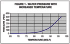
Water is virtually incompressible. When heated and expanded, pressure will increase suddenly and rapidly to dangerous levels in a closed-piping system. Figure 1 on page 34 shows the elevation in pressure with increasing temperature in an average plumbing system.
The pressure in the system will rise until a weak component in the plumbing system provides relief. This component could be a faucet washer, a weak pipe, poor solder joint, water closet valve, etc.
Due to thermal expansion-related problems, water authorities have recorded a skyrocketing increase in home and building maintenance personnel calls.

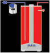
Figure 2
Common Symptoms
The most common symptoms that may indicate a thermal expansion problem exists include:- The water heater relief valve operating to relieve excessive water pressure.
- An excessive water pressure surge when a faucet is opened.
- Increased frequency of faucet washer replacement.
- Metallic expansion noises in the water heater.
- Piping noises, cracking or creaking while the water heater is operating.
- Premature failure of appliance solenoid valves and o-ring seals.
- Severely reduced water heater life.

Elevated pressures fluctuations may lead to dangerous conditions such as collapsed center flue way , resulting in carbon monoxide from incomplete combustion, and also the potential for flame roll out–a condition where the flame seeking oxygen exits the water heater laterally out of the water heater.
The Solution "
The solution to this potential liability problem must be accomplished in various stages.Stage 1 is to inform and educate. The building owner must be informed of the conditions occurring within the plumbing system, the potential dangers and the symptoms of the condition. Educate the building owner as to the acceptable solutions for properly controlling thermal expansion.Stage 2: Repeat Stage 1. The success of any program depends on a continual barrage of information about the installation and important maintenance requirements of the thermal expansion control equipment.
The plumbing codes accept approved and listed thermal expansion control tanks as the means for controlling pressures. Some authorities still accept secondary relief valves, although this inexpensive “quick fix” is not considered acceptable by energy-conscious conservationists.A major dilemma occurs when new maintenance personnel are hired in a building that utilizes an auxiliary relief valve.
Experience has shown that an uninformed maintenance worker will often plug the relief valve or remove it, restoring the system to its non-controlled state. In addition, the installation of safety devices such as secondary relief valves cannot be used as an operating control to intermittently release water from the system because any sediment collecting on the valve seat can cause continuous water-flow conditions, or worse, a totally blocked relief valve.
To prevent “collapsed flue,” thermal expansion tanks are designed as operating controls to limit pressure fluctuations caused by the water heating expanded water volume.
The thermal expansion tank acts like a “lung” on the piping system, accepting expanded water as the water heater functions. As water is used, it is pushed back into the piping system by the tank’s compressed air cushion. Typically, expansion tanks utilize a flexible butyl diaphragm or bladder to separate a sealed compressible air cushion from the incoming expanded water.
The air cushion is “pre-charged” to approximately 40 psig and retained by the flexible diaphragm. The expanded water enters the diaphragm, which protects the tank’s steel from the potentially corrosive fresh water. (See Figure 2 above.)
The proper thermal expansion tank size is critical in limiting the pressure fluctuations in a piping system. Too small a tank leads to high-pressure fluctuations; too large a tank reduces pressure fluctuations but creates cost constraints that may prove prohibitive.
The critical size requirement for any thermal expansion tank is based on the physical properties of water and the subsequent required air cushion needed to absorb the water within a specific pressure range. The tank size is calculated by using the following equation:
TX = Expanded Water
(P1/P2-P1/P3)
Where:
TX = Thermal expansion tank volume (gal)
P1 = Pre-charge pressure (PSIA)
P2 = Static line pressure (PSIA)
P3 = Maximum allowable tine pressure (PSIA)
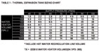
Thermal Expansion Tank Sizing Chart
To help water authority personnel, plumbing engineers, code officials and plumbing contractors in sizing based on the above equation, a quick sizing table has been developed for use. (See Table 1 on page 36.) To use the table, simply check the water heater volume in the left column and supply-line pressure along the top row. Trace down from the static pressure and over from water heater volume until the two lines meet.
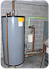
Water heaters, such as this indirect-fired unit, benefit from the use of a code-required expansion tank. Most water heater manufacturers void the warranty if thermal expansion control is not followed. Courtesy of Wessels Co.
Manufacturers will typically create sizing tables reflecting exact model numbers and requirements to satisfy critical sizing. When utilizing a chart of this type, ensure the sizing is based on the appropriate requirements. Protection of life and property are all at stake when thermal expansion is neglected.