
Our industry has used primary/secondary piping systems for years. Most engineers currently designing hydronic systems are familiar with how these systems operate, as well as how they are designed. Still, based on discussions I’ve had, it’s evident that questions remain, particularly on this issue of flow reversal when secondary circuit flow rate exceeds primary loop flow rate.
The notion of flow reversal runs counterintuitive to the idea of a single primary loop supplying heat to several secondary loops. It’s easy to conceptualize a primary circulator as having to produce enough flow to “feed” all the operating secondary circulators. However, this is not the correct way to look at primary/secondary systems. Although the primary loop does supply heat to each secondary circuit, it does not supply flow to each secondary circuit.Supplying heat to a secondary circuit is evidenced by a drop in temperature of the primary loop flow as it passes a pair of closely spaced tees. This is entirely different from supplying flow to the secondary circuit. In animated terms, the primary circulator “isn’t aware” of the existence of the secondary circuits and vice versa. Each circulator operates as if the circuit in which it is installed is completely isolated from the other circuits.
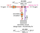
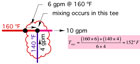
Figure 1shows a close up of the situation, along with the calculations for temperature drops.
Following the Energy
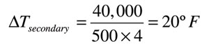
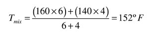
The best method for predicting the output of a situation in which multiple energy flows converge is to simply account for all energy carried in and out of the process. Just as the flow of water into and out of a tee must balance, the energy carried into a mixing point must equal the energy carried out of that point. This concept is based on the first law of thermodynamics.Since the secondary circuit load removes 40,000 Btu/hr of heat, the temperature drop in the secondary circuit is (see equation above):
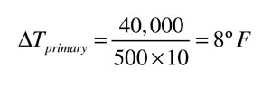
The temperature drop along the primary loop also can be determined by accounting for the fact that heat is being removed at the primary/secondary interface at a rate of 40,000 Btu/hr. Hence, the temperature drop in the primary loop is (see equation above left):
You might be wondering why the temperature drop in the primary loop is different than the drop in the secondary loop. It’s because of the different flow rates in these loops (10 gpm in the primary and 4 gpm in the secondary). Heat transfer into or out of a fluid stream is always based on the product of flow rate and temperature drop. For a given rate of heat transfer, when flow is increased, temperature drop decreases and vice versa.
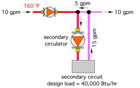
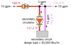
Thus, inFigure 2:
Overpumping Option
Now assume a circulator capable of generating a flow rate of
15 gpm was installed in the secondary circuit, and the piping was scaled up
accordingly. Figure 3 shows the resulting flows:<br><br>
Notice that flow between the closely spaced tees has reversed. This reversal is
the only possibility given the flow rates in the surrounding pipes, and rest
assured it does not damage the system in any way. <br><br>
Also notice that the flow rate in the primary loop, for all practical purposes,
does not change. That’s because the insignificant pressure drop between the
closely spaced tees effectively prevents the primary loop from “feeling” any
change in its hydraulic resistance. Remember, the primary loop doesn’t even
“know” the secondary circuit exits.<br><br>
An even more interesting result is what happens to temperatures and heat
transfer in the secondary circuit. Again, we have to follow the energy into and
out of the tees to predict what will happen.<br><br>
The flow reversal between the tees now creates a mixing point at the upstream
tee-just the opposite of what occurred in the first scenario where the mixing
point was at the downstream tee.<br><br>
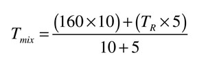
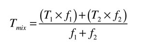
Where:
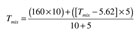
Tmix = supply temperature to the secondary circuit (°F)
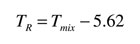
TR = return temperature from the secondary circuit (°F)
Unfortunately, we don’t currently know the value of the return temperature from the secondary circuit (TR), and without this, we can’t calculate Tmix. We can, however, make a couple more observations that get us out of this situation.
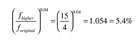
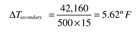
Anyway, let’s conservatively assume the load is now 5.4% higher (42,160 Btu/hr rather than 40,000 Btu/hr) due to the flow rate increase. It’s a conservative assumption because we already realize that the supply temperature to the load will be reduced because of mixing at the upstream tee.
The temperature drop across the secondary load is now (see equation above right):

Knowing this, we further recognize that the lower supply temperature also lowers heat output from the secondary circuit. How much? Here’s an estimate, again assuming the heat emitters are fin-tube baseboard and a room air temperature of 70°F.
The increased flow rate (by itself) increases heat output about 5.4%, while the decreased supply temperature (by itself) would lower heat output about 4.6%. In other words, it’s essentially a wash. One effect compensates for the other, and any net change in heat output is insignificant. Refer to equation above left.
So where does this leave us? Well, we’ve conceptually installed a larger secondary circulator and managed to reverse flow between the tees. However, for all practical purposes, we’ve not changed the heat output of the secondary circuit, nor have we changed the temperature of the water leaving the downstream tee. If we had installed this scenario, we would have wasted money on a larger secondary circulator as well as larger secondary piping. We also would have created a system that requires substantially more electricity to operate the larger secondary circulator for years to come. Over a typical 20-year design life, this added operating cost could approach or exceed $1,000. Is this a wise choice? Not in my opinion. By the way, if you installed a larger primary circulator under the premise it would prevent flow reversal, you are just wasting even more pumping energy.
We’ve seen that flow reversal is possible in a P/S system, but when it occurs, the heat transfer from the secondary circuit is mostly unaffected, as are the other secondary loads in the system. The only significant difference is a needless increase in both installation and operating cost for the oversized secondary circulator and piping. This is something our industry can do without. Pumping energy is a terrible thing to waste.


