
Solar heating systems are not a new concept in the United States. Many of you can remember the first "solar era"
The Fundamentals
Three principles must be observed when incorporating an active solar energy subsystem into a hydronic heating system. They are as follows:
- 1. The cooler the collectors can operate, the lower their thermal losses and the higher their efficiency.
2. Conventional energy sources (oil, gas, and electricity) should only be "invoked"
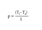
See Formula 1, where:
Ti = inlet fluid temperature to the collector (°F)
Ta = ambient air temperature surrounding the collector (°F)
I = solar radiation intensity incident on the collector (Btu/hr/sq.-ft.)
The higher the inlet fluid parameter, the more "severe"

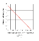
Figure 1 shows the corresponding efficiency to be 0.16. Hence, 16% of the solar energy incident on the collector is being converted into heat output. This is certainly not high efficiency, especially when compared to other hydronic heat sources. Such low efficiency is a direct result of forcing the collector to operate with a relatively high inlet fluid temperature during cold ambient conditions.
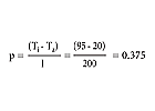
Under these operating conditions the collector efficiency is 0.43, or 43%. The significant drop in the inlet fluid temperature increased collector efficiency about 2.7 times. As you can see, inlet fluid temperature is extremely important. Keep it as low as possible for the best performance.
Principle number two also plays a big role in piping design. The system should allow the conventional energy source to supply the load without warming the solar storage tank. Doing otherwise decreases the collectible solar energy and increases tank heat loss. It also creates a situation where energy is being stored as heat rather than chemical energy. The former is obviously much more difficult to contain than the latter, especially over a period of several days.
The third principle is, hopefully, obvious to anyone who expects the solar collectors and exposed piping to survive past the first night in subfreezing temperatures.

Works Every Time
There are several ways of piping active solar energy systems. One key difference is how freezing is prevented within the collector-to-storage portion of the system.One approach moves heat from the collector array to the storage tank using a closed/pressurized circuit filled with an antifreeze solution. Heat is passed from the collector piping to the storage tank water through a heat exchanger.
Another approach operates the collector array with water, draining it and all exposed piping as freezing conditions approach. When the water is drained to waste, the system is called a draindown system. When the water is drained back to the storage tank, the system is called a gravity drainback system.
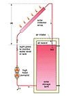
After working with all these approaches, my favorite is the gravity drainback system. When properly designed and installed, it eliminates the installation cost and thermal performance penalties associated with glycol-based antifreeze while providing an extremely reliable freeze protection scheme. (The schematic for a gravity drainback solar energy subsystem is shown in Figure 2 on page 30.)
In this design, water drains from the collectors and exposed piping, and runs back to the storage tank whenever the collector circulator stops. The captive air at the top of the tank moves back into the collector piping through an open side port tee installed a few inches above the water level whenever the collector circulator stops. No motorized valves or electronic controls are needed.
This is a closed-loop system. Once filled and purged, no water or air is added or removed (other than for very minor losses). The system can use cast iron circulators and be directly tied to a closed-loop hydronic distribution system. If properly proportioned, the air space at the top of the storage tank can also serve as the expansion volume for the system.
It is essential that the collectors and all exposed piping in gravity drainback systems be pitched a minimum of 1/4-inch per foot toward the storage tank to allow complete drainage.
It also is critical not to operate the system with an active make-up water connection as is common in other types of closed-loop hydronic systems. This is necessary for two reasons: First, if a small leak ever develops in the collector piping above the tank water level, the system could slowly fill with water, possibly to the level where freezing could occur in the exposed piping. Secondly, if the system has an active air separator, it will eventually gather and eject the supposedly entrapped air and replace it with water. Again, the likely result will be a costly hard freeze due to the inability to drain water from exposed piping.
I prefer to equip the system's central deareator with a shut-off valve to prevent it from expelling air after the system is initially purged. I also suggest that a double-ended hose be temporarily connected to add water to the system from the make-up water system if necessary, and then removed to prevent accidental filling. A sight glass should be installed on the tank or the up-going collector piping to check the proper level in the tank.
Over the Hump
The collector circulator in a gravity drainback system must be sized to lift the water to the top of the collector array. This can be accomplished several ways, depending on the vertical height between the top of the water level in the system when drained and the top of the collector array (Figure 3). This distance represents "lift head"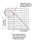
It is also important to maintain temperature stratification within the solar storage tank. This makes the hottest water available to the load and the coolest water available to the collectors. One way to do this is to install a "bullhead"

DHW Only
One of the most economically feasible loads for an active solar energy system is supplying domestic hot water (DHW). It's a year-round load, and thus takes advantage of high solar availability in warmer months. The size of the solar collector array for an average residential DHW load also is much smaller than that required for a high percentage of solar space heating.Since many residential hydronic systems have an indirect domestic water heater, it's natural to look at ways of using that tank for solar storage as well as a boiler-supplied water heater. Unfortunately, maintaining such a tank at a normal DHW supply temperature using conventional fuels violates design principle number two (keeping the solar subsystem operating temperature as low as possible).
Another issue is tank volume. A typical indirect water heater in a residential system has a volume of 30 to perhaps 60 gallons. For reasonably good performance, the solar storage tank should contain about two gallons of water for each square-foot of collector area. Solar energy systems supplying DHW for an average home can have 60 to 90 square feet of collector area, and thus need 120 to 180 gallons of water storage for optimal performance.
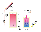
The indirect heater contains potable water in copper coils suspended in the insulated steel shell. The water in the tank is "system water"
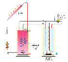
You also can preheat DHW using one or more suspended copper coils in the storage tank, as shown in Figure 7. In this configuration, cold water makes a single pass through the suspended coils and then flows into a conventional water heater. When the solar storage tank is hot, the suspended coils will likely provide all the heating needed.
At other times, the conventional water heater can "top off"
Running the Numbers
One of the best design tools for making detailed performance estimates of active solar energy systems is the F-chart Solar Systems Analysis program from www.fchart.com. The F-chart method was originally developed in the 1970s by S.A. Klein and W.A. Beckman at the University of Wisconsin-Madison. It is based on compilations of detailed, hour-by-hour simulations of active solar energy systems. The latest software implementation of the F-chart method can evaluate many "what if"Summary
Knowing how to integrate solar energy collection with conventional hydronic heating is a valuable asset to hydronic professionals. As fuel prices rise, prospective customers will increasingly request solar options. Be prepared to evaluate and integrate such options where appropriate.Reference manuals and CD sets from the 2006 MEC seminar series presented by John are now available at the AEC store at www.aecstore.com.
