Scalding is a traumatic event that always happens to someone else, on someone else's project, or in someone else's facility. This is much the way misfortunes of others are viewed on the 10 o'clock news. It can't happen to us because the odds are in our favor, and besides, all safety precautions are taken, "anti-scald"
Scalding Already Makes Headlines in 2006
Scalding can and does happen. And when it does, the consequences are devastating, often resulting in fatality or serious injury. The costs, the liabilities, and more importantly, the pain inflicted on the victim and victim's family are immeasurable.In just the first few weeks of 2006, two major scalding cases have gained national awareness, one in the U.S. and one in Canada. In Redwood City, CA, a nursing home is now being sued by San Mateo County for leaving a disabled woman in 135°F water for over 20 minutes. She will remain on a feeding tube for the rest of her life. Remember, it only takes three seconds at 140°F to obtain a third-degree burn. At 150°F, it takes only a single second. It happens that fast.
Was negligence involved? Absolutely, but why was 135°F water flowing from the tub in the first place? Lack of maintenance, absence of temperature sensing valves, handle rotation stops not installed or properly adjusted, valve failure upstream?
In Edmonton, Alberta, Canada, an 84-year-old woman died as a result of being lowered into a tub of 140°F water by a nursing home attendant. She suffered second-degree burns over 25% of her body. The nursing home and two health aides were named in the lawsuit.

New Valve Design
There are many factors that impact new valve design and innovation. New product applications, new technologies, solutions to existing problems, new standards, the list can go on. In light of the fact that thermostatic or temperature-sensing valves now dominate ASSE's water tempering standards, the focus of this article will center on design developments for these types of valves. (See Figure 1.)ASSE, New Applications Impact Design
In just the past three years, the American Society of Sanitary Engineering (ASSE), the organization that overseas standards development for the performance of water tempering valves in the interest of public safety, has been very busy. It has revised two of its major standards (1016-showers and 1017-distribution), issued two new standards (1069-gang showers and 1070-lavatories), and has another pending for release (1071-emergency valves).
Although ASSE does not dictate product design ("The major consideration in constructing an ASSE standard is fundamentally: what a product is to do, not how it is to do it"

ASSE 1069 demands what is essentially ASSE 1016-T control to gang showers or other multi-unit, single temperature applications. Large shower rooms will require higher capacity valves (than those currently available), similar in capacity to ASSE 1017 valves, but with tighter control and responsiveness to pressure, not just temperature. Manufacturers are already responding with new products and new designs to meet this requirement.
At the Heart of Every Design
When the first pressure-compensating valve was patented back in 1929, not many would have imagined, almost 80 years later, it would still be the most common form of tempering for commercial and residential bathing applications.The 1929 patent was for a spool and sleeve design, still used by some today. The diaphragm and poppet design is also widely manufactured. Both have benefits for those applications where pressure protection is the only consideration. The designs themselves have been around for decades, with ongoing improvements, but these valves operate with the same essential mechanisms as their earliest predecessors.
For those that wanted a higher degree of safety, the thermostatic valve (ASSE 1016-T) offered protection from temperature as well as moderate pressure changes, but at a premium price. And for even greater protection, the combination valve (ASSE 1016-T/P) was developed, offering full protection from temperature and pressure disturbances, but for most, at a prohibitive cost.
Recent advancements in thermostatic technology and valve design have vastly improved product performance and dramatically reduced cost. To understand these advancements, it is best to start with the technology itself, i.e., what's at the heart of a valve-the tempering mechanism.
There are essentially three basic temperature-sensing mechanisms: bi-metal (coils or discs), chemical (ether) filled and paraffin or wax. The first two, bi-metal and chemical filled, are the traditional approaches to sensing and reacting to temperature shifts. The latter, paraffin (with copper), is the most prominent technology for smaller valves (and the newer ASSE standards), and has recently been pioneered into the large master tempering valves. It is ideal for large valve design because its smaller size and speed of response translate to superior low flow accuracy.
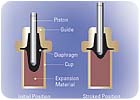
The sensor, while small in size, is powerful in force. As the water surrounding the sensor increases in temperature, the paraffin/copper charge increases in volume (solid to liquid), thus moving the piston in an upward direction. This movement, as a component of a valve's operating mechanism, restricts the flow of hot water while proportionally increasing the flow of cold. When the water enveloping the sensor cools, just the opposite effect takes place. An opposing spring contracts the sensor, moving to close the cold-water supply while opening the hot. The reaction of the sensor to changes in water temperature and supply pressure occurs nearly instantaneously.
This is critical to new valve design because engineers are now demanding cost-effective, low flow control solutions over a broader range of flows and at lower pressure drops. Larger mixing valves have always struggled with low flow, hence the development of two- and three-valve systems. The small valve controls at lower flows, the large valve controls at higher flows. Now, as valve design and technology have evolved, a single-valve can accomplish both. Single-valve solutions translate to better performance (no PRV), much lower cost (one valve instead of two) and fewer opportunities for problems (elimination of leak points, pressure loss) associated with extra piping.
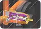
Bath and shower valves are now being designed to accept different technologies based on a facility's desire to have one technology for one application and another technology for a different one. This newer design also allows for a fast and easy upgrade from one valve type to another. First brought to market four years ago, a valve may be installed with a pressure-balancing cartridge, which could be easily converted to a thermostatic or combination valve. Swapping one cartridge/technology for another takes only a matter of minutes. Most other components of the valve are identical, so maintenance can minimize inventory SKUs for repair, even with two different technologies in a facility.
Packaging and Design
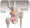
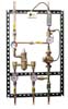
To insure proper recirculation, manufacturers are making it easier for engineers by packaging tempering valves with pumps, aquastats, alarms and balancing valves, all pre-assembled and factory tested, secured to welded struts. (See Figure 6.) These self-contained tempering and recirculation stations allow engineers to specify a single model number instead of one for each component in the system. These contractor-friendly units save time, money and optimize valve performance for safer water distribution and return through a facility's plumbing system.Critical to these packaged solutions is a new tempering valve that is installed on the return line. The valve's function is to sense return water temperature, and dependent on that temperature, proportionally divert it back to the cold side of the valve or to the boiler. This prevents temperature creep under low and no demand scenarios. If the water temperature is below the set point, the balancing valve automatically sends a greater percentage of return water to the boiler, thus supplying the valve with ample hot water to achieve loop temperature. If above the set point, a greater proportion is diverted back to the valve (and away from the boiler), again to maintain loop temperature.
This "automatic balancing"