Issue: 3/05
Snowmelting systems have gained a widespread acceptance in all sectors of our industry: residential, commercial and industrial. Residential snowmelting systems can alleviate shoveling, plowing and plow damage, sanding and salting. Typical application areas are driveways, walkways, patios and steps. Commercial snowmelting applications reduce liability and improve accessibility. Clean sidewalks will attract customers, and most importantly, provide safety. Snowmelting systems are an excellent choice under pavers (chemical melt aids, plowing and shoveling are difficult due to joints). Typical commercial application areas are building entrances, parking ramps and lots. Industrial snowmelting applications are used where safe, clean and easy access is critical. Typical application areas are hospital emergency entrances, helipads, loading docks and building entrances.
The design of the snowmelting system is fairly straightforward when it is broken into the following nine steps. In most snowmelting applications, these major steps are used. With every job a designer or engineer designs, he or she becomes more familiar with the design procedure.
Selecting the Design Criteria Level
The first step to designing snowmelting systems is to define the customer's intention and expectation of the snowmelting system in order to select the correct design criteria level. There are three main levels.
- Level 1 is designed to keep the surface completely free of snow 95% of the time. Typically, 5/8" PEX tubing with 9" spacing (1/2" for small areas) is used. Some common applications are residential applications, driveways, sidewalks and hot tub areas.
- Level 2 is designed to keep the surface completely free of snow 98% of the time. This is the typical level selection for most cases and uses 5/8" PEX tubing with 6" or 9" spacing (3/4" for large areas). Some common applications are commercial and light commercial applications, public access areas to buildings, handicapped ramps and commercial stairways.
- Level 3 is designed to keep the surface completely free of snow 99% of the time. Typically, 5/8" PEX tubing with 6" spacing (3/4" for large areas) is used. Some common critical applications are hospital emergency ramps, helipads, access areas for emergency vehicles (fire stations, etc.), and areas deemed critical for public safety.
Calculating the Snowmelting Load
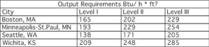
To calculate the heat output required for snowmelting areas, ASHRAE published a table that shows heat output requirements for different geographical areas (Table 1).
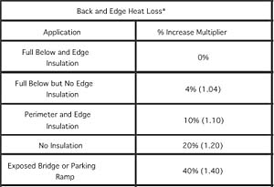
Use Table 2 to calculate the back and edge heat loss.
Calculating the Tube Spacing
Tube spacing is a vital element of designing a snowmelting system. Decreasing the tube spacing will allow the snowmelting system to operate at lower fluid temperatures while meeting the heat output requirements. Depending on the construction of the thermal mass, the spacing should be adjusted in certain applications. Space the tubing 1 inch closer for each inch of concrete cover greater than 2 inches. Space the tubing 2 inches closer for each inch greater than 2-3/8" pavers. Space the tubing 1 inch closer for asphalt applications (minimum of 6" spacing).
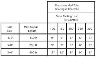
Use Table 3 to calculate the proper tube spacing.
Calculating the Fluid Supply Temperature
A glycol/water solution is used in the snowmelting system. The supply fluid temperature directly correlates to the snowmelting system heat output. Typical water temperature for a snowmelting system is 130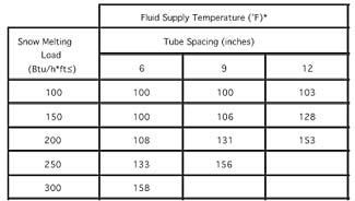
Calculating the Number of Circuits
The first step to calculating the number of circuits is to estimate how much tubing will be used in the snowmelting system. Use Table 5 to calculate the amount of tubing needed. This table adds approximately 10% for leader length (supply and return tubing from the snowmelting area to the manifold).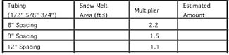
To avoid waste and to have equal circuit lengths, a carefully planned layout should be done. First, determine where the manifold should be installed. Remember the manifold must be accessible. When calculating the number of circuits, always round up! To simplify balancing, keep the length of each circuit the same in the snowmelt area.
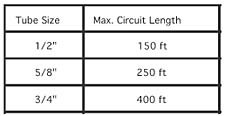
To calculate the number of circuits:
Total amount of tubing ÷ Maximum circuit length = # of circuits
Calculating the Flow Rate
In order to size the pump, the flow rate for the system must be calculated. By reworking the energy transport equation, the flow rate can be calculated. In order to use this equation, the total heat output must be calculated first.Total heat output = snowmelting load per square foot x area of snowmelting system
Use this equation to calculate the flow rate of water with 0% Glycol:
GPM = Total heat output ÷ (500 x delta-t)
Use a delta-t of 30
Calculating the Pressure Drop
The next important step to sizing the pump is to calculate the pressure drop. Use Figure 1 to determine the pressure drop through the longest circuit length with 0% glycol. If the pump can overcome the pressure drop in the longest circuit, it can overcome all other shorter circuits. Use the flow rate per circuit value to find the pressure drop. The pressure drop from Figure 1 is given in feet of head per foot, so this value must be multiplied by the maximum circuit length.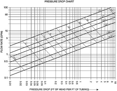
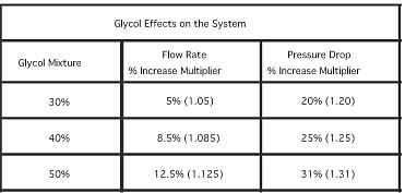
Adjusting the System for Water/Glycol Mixture
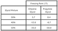
Freeze protection is essential to the snowmelting system. For typical applications, I recommend using 40% Propylene Glycol. Ethylene Glycol is acceptable. Use Table 7 to determine the freezing point of the water/glycol mixture based on % glycol by volume.
Automotive antifreeze is not recommended; the silicates in automotive antifreeze can coat and foul heat transfer surfaces and plug the system, reducing energy efficiency. The material properties change according to the % glycol mixture. Use Table 8 to adjust the flow rate and pressure drop calculated through the tubing.
Selecting the Pump
The pump must have a capacity equal to the system flow rate and a head equal to the system pressure loss. These two system characteristics are the primary ones in selecting a pump.
Remember to use the highest pressure drop of all the circuits fed by their circulator. If the circulator can overcome that pressure drop, then it can overcome all the others. Pump performance varies with temperature and viscosity of the water/glycol solution. It is important to use the adjusted flow rates and pressure drop values to take into account the glycol/water mixture. Refer to the pump curve chart from the pump manufacturer for detailed performance characteristics. Remember, the calculations mentioned here only took into account the tubing pressure drop. Pressure drops of other components, such as the valve, heat exchanger, hard copper piping, etc., must be added in.