Issue: 9/04
Once upon a time, sprinkler drawings were a work of technical art. They embodied hours of painstaking love and passion. Designers used pencil and paper taped to wooden drafting boards to create meticulous drawings. Each drawing was different. It bore the individual designer's personality, his trademark, to the extent that one could identify the designer based on the art and lettering. Those days are rapidly drawing to a close as industry is swept into the information age. We are in an era of obsession with productivity that threatens to blur the distinction between workers and machines. It is possible that CADD systems may someday replace manual drafting and the old drafting board. However, the extent to which this can be efficiently achieved depends on the effect that CADD will have on the design production function. Some see CADD as a nefarious conspiracy to create a "brave new world" run by technocrats bent on making designers obsolete. Others see it as freeing them from mundane and repetitive tasks best done by machines, thus allowing designers to focus their energy and creativity on the design process. But is CADD different from other technologies?
CADD is not much different from other innovations that have emerged in the course of economic history. Under the right conditions, it could expand corporate profit margins by increasing worker productivity. This paradigm is at the core of the internal logic that propels the capitalist system. While a lot has been written and said about various CADD systems, there has been little discussion about the fundamental technical and economic factors governing the successful application of CADD in the sprinkler industry. A CADD design system can be analyzed using an engineering economic model known as the production function. Its success depends as much on the choice of computer technology as it does on the skills possessed by the fire sprinkler designer.

The Production Function and Economies of Scale
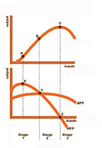
A production function can be defined as ""CADD Technology and Design Productivity
CADD is replacing traditional methods of fire sprinkler design. A major rationale for this appears to be the savings possible from the accuracy, ease and speed with which changes and corrections can be made to an electronic drawing. Another major justification is automation, i.e., material lists and hydraulic calculation modules are linked to changes in the drawing. In addition to the standard editing functions, some CADD systems support macros and programming languages. The decision to adopt CADD technology cannot be based on flashy product brochures and sales demonstrations. It must be grounded in an acute understanding of the various elements that affect the CADD production function. There are both technical and human barriers that need to be overcome to maximize efficiency and output from the application of CADD technology.Digital Drawing Preparation
The starting point of fire sprinkler design has remained basically unchanged over the years, i.e., fire sprinkler drawings begin with project drawings. Those are produced by a host of contractors from other trades involved in the project-architectural, mechanical, HVAC, electrical and plumbing. If the plans are only available as paper drawings, they must be scanned into a bitmap or raster format and then digitized to a vector format suitable for use by the CADD drawing platform. It is important to get all the plan drawings in a vector format. The scales and dimensions in the converted drawings must accurately match those of the other drawings when overlaid. This is one of the most important and labor-intensive stages in designing fire sprinklers. If the project is relatively small, e.g., where a few heads have to be moved in a tenant improvement, it may be more efficient to use manual drafting.
A fire sprinkler CADD drawing is usually organized by layers. Each layer represents a distinct element of building construction-a layer for the reflected ceiling plan, another layer for the structural plan, a separate layer for the HVAC plan. However, since there are currently no layering standards that can be enforced between the trades, a structural steel drawing and its attributes must be manually assigned to the correct layer. The operator must also ensure that symbols and their dimensions show up correctly. This makes it possible to accurately place the pipe relative to the structural elements and to automatically cut hangers and place earthquake bracing. For a "center-of-tile" placement of sprinkler heads, the drawing module requires that the reflected ceiling plan be placed on a specific layer for accurate processing. One solution is to draft and implement the type of drawing and layering standards that are required on some government projects (http://home.ncifcrf.gov/fme/pdfs/generalspecs/GS-01.pdf).
The Cult of AutoCAD
It is impossible to discuss CADD technology without citing AutoCAD and its influence on current CADD technology. AutoCAD is a popular CADD program from AutoDesk Inc. of San Rafael, CA. It boasts more than 1.2 million users and now presides over a vast CADD imperium. Its influence on the technical drafting market has been so pervasive that practically all architectural and engineering plans are now drawn in AutoCAD's proprietary DWG format. State and federal agencies often require data to be stored in the AutoCAD DWG file format, which until recently was difficult to convert.CADD drawings are usually distributed in two vectorized formats: DWG and DXF. The DWG file is a proprietary format owned by AutoCAD. The DXF file is a generic format designed to facilitate the exchange of drawings between AutoCAD and other CADD systems. This all works well if you draw with AutoCAD. Otherwise the DWG or DXF files you receive may lose important drawing elements when imported into your CADD system. If the missing elements are important, they must be added to the drawing. The conversion of fonts can be a particularly difficult problem. The DWG file format changes each time a new version of AutoCAD is released. This means that newer files must be converted before they can be loaded into older versions of AutoCAD. Drawings originally rendered in AutoCAD may not be accurately displayed when loaded into other CADD systems. There are now many CADD programs that easily surpass AutoCad in speed, usability and price. Some architects and engineers find Bentley's MicroStation™ to be much better than AutoCAD. Bentley has developed a method for converting its DGN files to DWG. However, they don't have a sufficiently large share of the market to interest developers.
Nearly every CADD system has faced problems sharing drawing data using DWG. One solution is an open DWG standard. The Open Design Alliance™ has been promoting an open file format named OpenDWG (http://www.openDWG.org). The Alliance hopes to make DWG the industry standard and are pooling their resources to create better conversion tools for other CADD systems. OpenDWG addresses the problems of importing DWG files into popular CADD systems such as Visio2000 (http://www.design-drawing.com/visio/AcadVsVisio.htm). They provide libraries that can be downloaded from their Web site to make it easier for other software to import and edit DWG files. AutoCAD has refused to join the Alliance, one of many instances in which AutoCAD has used its power to limit choice and reduce CADD system productivity.
Drawing Modules
AutoCAD boasts a rich set of drawing tools and programming environments. However, it has an arcane command structure that makes it difficult to master. The number and complexity of commands seem to be growing exponentially with each new release. AutoLISP is a programming language built into AutoCAD. It supports a large and versatile array of drawing functions, but AutoLISP is also illogical and error prone. AutoCAD also supports Visual Basic Applications (VBA), which is more robust than AutoLISP, but is slower and requires programming skills. There is also support for Visual C++ but it demands more sophisticated programming abilities. There may be relief on the horizon in the form of modules that work with AutoCAD to simplify and automate the design process. A drawing module simplifies the process by providing menus and commands specifically tailored for the purpose. But are these modules as productive as they claim to be?A drawing platform such as AutoCAD is more useful if each drawing element can be assigned a tag, e.g., an open circle that represents a type of sprinkler head can be made to store information about its make, type, size and K-Factor. A drawing module helps by dedicating a symbol to represent a type of sprinkler head, which it then places on a specific layer. The symbol can be processed to generate a material list. A drawing module can thus be thought of as a device that aids in the development of a drawing database. The process is deliberate and meticulous, which leaves little room for error. And even if everything is done right, a software bug could create a problem.
A good deal of training is required to achieve accurate results. Some module developers charge their customers up to $1,000 in training fees, and it could take a designer up to a year to attain proficiency in using the module. Some designers find the drawing modules too restrictive and prefer to rely completely on AutoCAD. If the listing module fails, they complete the material lists by hand. The hydraulics are then performed separately using a stand-alone application. Most companies have a healthy mix of drawing modules from various developers and a backup plan in case of problems. This is as true for word processors as it is for CADD design modules. Our experience indicates that few companies are able to take full advantage of the productivity potential opened up by any kind of software.
Hydraulic Calculation Modules
The hydraulic calculation is probably the single most important step in the design process. But it may also be the weakest link in CADD-based design. For the resulting calculations to be accurate, there must be a perfect exchange of data between the drawing and the calculation modules. The hydraulic module must accurately extract all relevant piping information between the most remote area and the point of connection to the water system. This includes data on elevation, K-factor, pipe diameters, pipe lengths, fittings and C-Factors.This rarely happens without a hitch. If there are errors in the choice of symbols or their placement on layers, the data will not be correctly extracted, and errors will result. There may also be software bugs in both the drawing and hydraulic modules that could lead to serious errors.
The drawing modules usually extract and save hydraulic data in formats that can only be used by their own hydraulic modules. This leaves little room for choice if users have a preference for modules or stand-alone applications from other developers. The modules are rarely as good as most stand-alone hydraulic calculation applications currently on the market. Which explains why stand-alone hydraulic calculation software is still being sought out by companies that have purchased and installed the "complete" CADD modules. In addition to being an added expense, it also adds a series of manual steps that defeat a major benefit of automation-fire sprinkler hydraulics that are tied to the drawing database and that require little or no manual intervention. Is there still a place for humans in this brave new world of CADD technology?
The Designer
In most engineering fields, CADD operators are supervised by an engineer, or a team of engineers, in charge of the project. They have few other job responsibilities. In fire sprinklers, the story is vastly different. Fire sprinkler designers must understand NFPA and FM fire codes and be familiar with local fire sprinkler ordinances.They are also required to take charge of coordinating their fire sprinkler plan with all the other trades working on the project, and must submit and obtain approvals on their drawings. They are in charge of the design from start to finish. Some sprinkler contractors even require their designers to perform the field installation. Others are so small that the designer is, by default, also the installer. Far from replacing the sprinkler designer, the CADD drafting system enhances the designer's level of responsibility and importance.
Acutely aware of the widespread demand for CADD operators, designers may be tempted to leave for higher paying jobs in other fields or accelerate wage demands in their current occupation. This is the most plausible explanation for the large number of calls that we have received from besieged fire sprinkler contractors all over the country. These companies are in limbo for weeks or months at a time because their CADD designer left for a higher paying job. A designer that quits must be replaced if a sprinkler contractor is to remain in business. The replacement may have to be trained or retrained to use AutoCad and the design modules. It is one of the ironies of life-a $20,000 CADD system remaining idle without its human operator.
The introduction of a CADD system, while empowering, also requires that sprinkler designers bear a greater burden of involvement with CADD system hardware and software. Files are easily lost on a computer. A malfunctioning or "crashed" hard drive, badly handled magnetic media and power failures can all contribute to a loss of valuable data. Since most sprinkler contractors cannot afford to hire MIS professionals to manage their computers and data, such responsibilities often fall on the sprinkler designers. They are responsible for storing and backing up all the electronic files pertaining to their projects. Designers must learn how to diagnose and defragment hard drives to prevent hard disk crashes. A loss of files can be disastrous to the entire project. It should be obvious by now that the skilled human labor component, L, is clearly the single most important element in the CADD production function. It plays a pivotal role in each and every one of the factors that affect CADD productivity. The introduction of a CADD system poses a series of challenges that require human ingenuity to overcome.
Whether it involves finding a way to cope with the perplexing problems of converting DWG files or using a design module, the path to maximum productivity depends on the skills and experience of the human operator.
The World Wide Web
The Internet has become a major conduit for the efficient and rapid exchange of DWG, DXF and other documents between contractors that may be located in different states or continents. The Internet can be used to instantly transmit drawing revisions to contractors located anywhere on the planet. Almost all drawing files and project documents are now sent as e-mail attachments or downloaded from servers via File Transfer Protocol (FTP). Such transfers also provide a path for the transmission of viruses, worms and spyware. Computer networks are under constant attack by a variety of threats perpetrated by hackers. These threats can bring entire networks, and even the entire Internet to a grinding halt (Wong, S.H, 2004, p. 42).
The Internet will make it possible for a multitude of networks to be interconnected so that designers from different trades can collaborate on a single set of electronic drawings located at a central server. Collaborative CADD could profoundly alter the future of fire sprinkler design.
Collaborative CADD Is the Future
One of the central problems that has confounded fire sprinkler contractors and designers is the fact that they have little or no control over the design of buildings requiring fire sprinklers (Wong, S.H, 2002, p. 19). Despite all the knowledge and sophisticated CADD technology at their disposal, fire sprinkler contractors watch helplessly as their frustration mounts and their profit margins dwindle. The construction industry, which is dominated by architects and engineers, has evolved a technocratic caste structure that relegates fire sprinkler companies to the pariah podium. Fire sprinklers are rarely ever considered an integral part of building design. So, after getting the drawings, fire sprinkler contractors struggle to figure out how they are going to run all that piping through the limited volume of precious real estate already colonized by structural framing, air conditioning ducts, water pipes, sewer piping and electrical conduits. There is little or no real collaboration between sprinkler contractors and the other participants involved in building construction.Nothing seems to have changed from the old days, except that today drawings are rendered in AutoCAD.
Collaborative CADD could play a useful role by offering a fully interactive environment for designing buildings in a manner that responds to the unique requirements and problems faced by all the trades involved in the construction project. The technology for this partnering already exists, but it calls for a toppling of the existing class structure, dominated by close-minded technocrats. Fire sprinkler contractors could then become equal partners in all the phases of building design and construction. That is the point at which the full potential of CADD productivity may be closer to being realized.

