For as long as hydronic radiant heating has been installed, the length of the tubing circuits has been a factor in performance. Rules of thumb have been developed by various sources. Some are based on thermal performance; others are based on limiting the pressure drop of the circuits.
Those that have installed radiant panel circuits without regard to maximum circuit lengths usually get an uncompromising lesson in fluid mechanics and heat transfer. Our office has received numerous calls on situations where 1,000-foot coils of 1/2" tubing have simply been unrolled into one long radiant panel circuit. Although there are "Band-aids"
An Accurate Performance Model
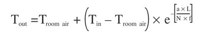
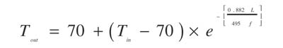
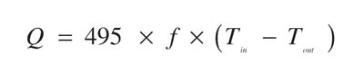
Designers often think of a radiant floor piping circuit as operating at an average water temperature. They assume this temperature is one half of the circuit's temperature drop below the supply temperature. Although this is a reasonable approximation, a more precise model considers the fact that the temperature of a small quantity of water drops as that water moves inch by inch along the circuit. This can be properly accounted for using Formula 1.Where:
Tout = outlet temperature of the panel circuit (

- 1. The circuit's temperature drop is strongly dependent on circuit length. The longer the circuit, the greater the fluid's temperature drop. For example, the temperature drop of a 100-foot circuit would be about (110 - 103.5) = 6.5
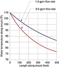
The temperature drop of the 500-foot-long circuit at 0.5 gpm is about (110 - 77) = 33
Where Are the Limits?
Once a designer has an accurate model for simulating performance, the next logical question is when does the circuit temperature drop become excessive? For example, would the 33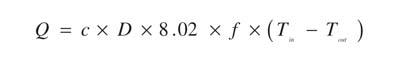
Formula 2, where:
Q = heat output of circuit (Btu/hr)
Tout = outlet temperature of the panel circuit (
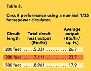
Using this formula, the heat output from the 500-foot circuits shown in Figure 2 would be as follows:
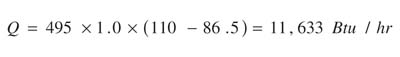
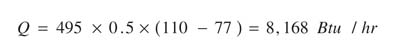
Although the temperature drop of the circuit operating at 0.5 gallons per minute is higher than that of the circuit operating at 1.0 gallons per minute, the total heat output of the circuit is lower.
Radiant floor circuits operating with temperature drops higher than, say, 35
Hydraulic Performance
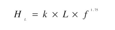
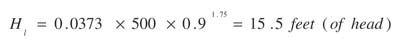
Another factor to consider when limiting the length of radiant panel circuits is the head loss (and associated pressure drop) of the circuit. The head loss of PEX or PEX-AL-PEX circuits can be estimated using Formula 3.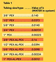
HL = the head of the piping system (feet of head)
k = a number based on tubing type/size found in Table 1
L = length of tubing circuit (feet)
f = flow rate through circuit (gpm)
If a 30% propylene glycol solution is used, multiply the values in Table 1 by 1.19. If a 50% propylene glycol solution is used, multiply the values by 1.35.
Pushing the Envelope
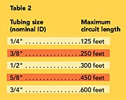
Various references give different suggested values for maximum radiant panel circuit lengths based on tube size. Some give a range for maximum circuit length, such as 250 to 350 feet when using 1/2" tubing. This recognizes the fact that there is no magic number for circuit length at which the circuit simply stops working. Instead, there is a gradual increase in temperature drop and heat output as circuit length increases.Table 2 gives relatively conservative maximum circuit lengths for various sizes of PEX or PEX-AL-PEX tubing:
These lengths provide reasonable circuit temperature drops and flow rates using traditional small circulators. For a given circulator and inlet temperature, the shorter the circuits, the lower their temperature drop from inlet to outlet. This is beneficial because it raises the average circuit temperature, and therefore, it allows the circuit to deliver more heat output per foot of length.
The drawback of shorter circuits is more manifold connections, as well as the likelihood of more "leader"

This configuration was evaluated for different circuit lengths and circulator configurations. All circuits were assumed to be 1/2-inch PEX tubing installed at 12-inch spacing in a 4-inch concrete slab with a bare surface. The supply water temperature to the manifold remained constant at 105
For the cases simulated here, the small circulator wattage is approximately 84 watts versus 206 watts for the larger circulator. Assuming 3,000 operating hours per year, and a constant $0.10/kilowatt-hour electrical cost, the difference in operating cost over a 20-year design life will be at least $732! This is a very significant added cost if the larger circulator is used solely to compensate for longer tubing circuits.
Summary
Results obtained from computer simulations of relatively long floor heating circuits show that acceptable thermal and hydraulic performance are attainable. In situations where slightly higher variations in floor surface temperature are acceptable, such circuits allow cost reductions while still delivering the necessary heat. Applicable projects include manufacturer facilities, warehouses or vehicle service buildings. When properly applied, longer radiant floor circuits represent good value engineering.* The Hydronic Circuit Simulator is one of several modules in the Hydronics Design Studio software available through www.hydronicpros.com.
