

Update (Jan. 2020): Click here to watch the Facebook Live video with John Siegenthaler (the author) on this same topic.
Designing high performance hydronic heating systems involves a knowledge of fluid mechanics, electricity, heat transfer and control theory.
Designing high performance hydronic heating systems requires a good understanding of fluid mechanics, electricity, heat transfer and control theory, not to mention a myriad of architectural issues. It's a field where there's always something new to learn and consider for future jobs. Regardless of how long you've been at it, this knowledge helps you make each new system better than the last.
As they gain experience with hydronics, new engineers learn to dissect what first appear to be hopelessly complex assemblies of pipes, wires, valves and boilers into various sub-systems, each with their own specific task. Within these sub-systems they learn to spot details and design concepts that are common to all top-performing systems. These are the details and design concepts that make the systems reliable, quiet, energy efficient and well-controlled; that hold true regardless of what manufacturer's products get specified; and that eliminate expensive surprises on the job.
This article discusses several such details and design concepts in the form of "do's" and "dont's." While they certainly don't represent everything a good designer needs to know, they do represent time-tested strategies that no hydronic system designer can afford to ignore.
The Do's
Do #1. Pump away from expansion tank. This has to be one of the most frequently emphasized details of modern hydronic heating. It still amazes me how it faded into semi-obscurity, especially its use on smaller systems, between when it was first postulated in the 1950s, and when it was "rediscovered" by the hydronics industry a few years ago (thanks largely to the efforts of Dan Holohan).
If you're involved in hydronics and haven't heard of the advantages of positioning the system circulator(s) to pump away from the system's expansion tank, stop what you're doing and don't design another system until you have a clear understanding of this essential concept.
In short, the objective of "pumping away" is to get the differential pressure produced by the circulator to add to the static pressure in the system. This makes air vents work better, reduces the chance of cavitation, quiets the circulator, and, almost without exception, "cures" systems that have suffered--perhaps for years--from chronic air problems. So many potential problems simply go away when you pump away.
Do #2. Take steps to suppress gravity flow. Any piping loop connected to a source of warm water and having a vertical displacement has the potential to for "gravity flow." As designers, it's easy for us to become so focussed on pumps that we forget that nature has her own agenda regarding when and where hot water should move through our piping systems.
The following pointers are all "do's" that can stop gravity flow from carrying heat where it doesn't belong:
-
Install a flow-check valve (or spring-loaded check valve) near the outlet of the heat source. Either type of valve stops hot water from sneaking out of the boiler until the circulator starts. A swing check is not an acceptable substitute since it offers no resistance to forward flow.
-
In systems that combine space heating with indirect domestic water heating, layout piping between the boiler and indirect heat exchanger so heat can't migrate into space heating piping during warm weather. Customers get justifiably upset when they feel any warmth emanating from their radiators while their cooling system is on. Wouldn't you?
-
Protect indirect DHW tanks from creating convective loops through their own heat exchanger and external piping after that piping has cooled off. A tank full of hot water with an adjacent piping loop is just begging Mother Nature to set up a convective loop. Install a flow-check valve to keep the heat where it belongs--in the tank.
-
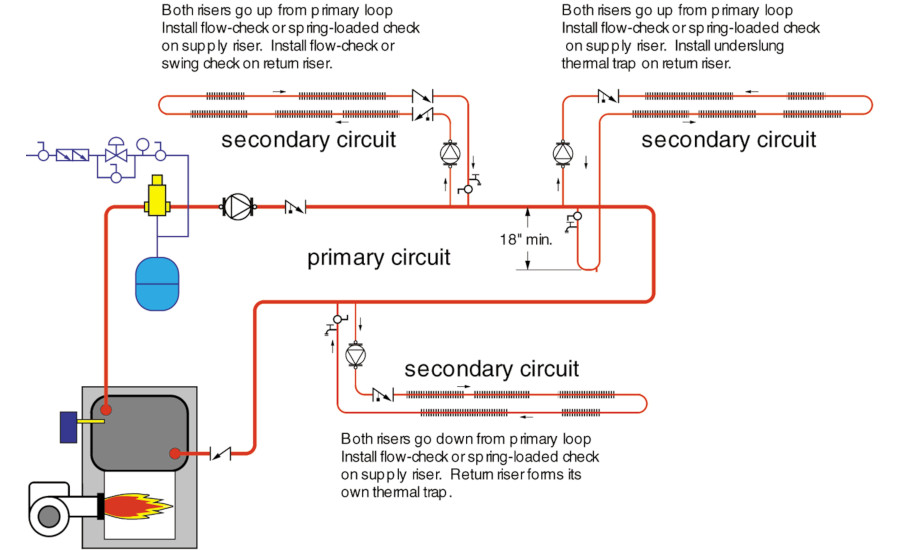
All secondary circuits connected to a primary circuit should have a flow-check valve or spring-load check valve on the supply, and one of the following options on the return: 1) another flow-check valve, 2) a swing check valve, or 3) an underslung thermal trap at least 18" deep. These options are shown in the schematic of Fig. 1.
> FIGURE 1.
-
Install zone valves on the supply side of zone circuits to block upward gravity flow. Install a swing check valve on the return side of each zone to block the return side. The latter is necessary because buoyancy forces try to establish two-way flow in the return pipe.
Do #3. Install controls to protect conventional boilers from condensation. All hydronic systems that pair a "conventional" boiler with a high mass distribution system operating at lower water temperatures should include a means of protecting that boiler from sustained flue gas condensation.
Cool distribution systems with high thermal mass (such as concrete floor slabs) can extract heat from the water flowing through them several times faster than the boiler can replace it. When this occurs, the only possible outcome is a rapid decent in water temperature, often well below the dew point of the exhaust gases. This allows sustained flue gas condensation and subsequent corrosion of the fireside surfaces, as well as flue piping.
There are several ways to protect the boiler from sustained flue gas condensation. All of them require a device that senses boiler return temperature and then regulates the rate of heat flow from the boiler based on this temperature. Without such temperature sensing (either mechanical or electronic), it's impossible to protect the boiler during transient conditions.
Most modern electronic mixing controls include boiler return protection as part of their programming. When such controls sense low boiler return conditions, they partially close the mixing valve, or slow the speed of the injection pump, to prevent the distribution system from stripping heat out of the water faster than the boiler can produce it.
Contrary to what some first think, boiler return protection doesn't slow the rate at which the distribution system warms up. Why? Because the boiler is firing continuously during the warm up process. It's putting out all the heat it can during this time, and the mixing device is routing 100% of that heat out to the distribution system.
Do #4. Install gP bypass valve on parallel zoned systems. The ability to extensively zone heating distribution has long been heralded as a major advantage of hydronic systems. At first, the concept appears so simple: Just install an electrically operated valve for each zone and open a given valve when its zone needs heat. Too often overlooked is the increased pressure differential across the circulator each time a zone valve closes. Left unchecked, high differential pressures can lead to flow noises, overheated pumps, flow leakage in other (closed) zone valves, and even erosion of piping materials.
The solution in small to medium size systems is to install a differential pressure bypass valve across the supply and return mains of the distribution system. In effect, this valve "caps" the upper differential pressure across the mains.
On larger systems, circulator speed can be adjusted using a variable frequency drive (VFD) to maintain differential pressure within prescribed limits. In addition to regulating pressure, this approach reduces energy consumption of the pump under partial load conditions. Look for variable speed distribution pumps to be available for smaller residential and light commercial applications in the near future.
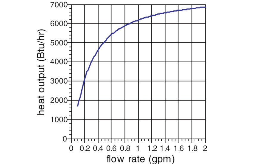
Do #5. Use valves with equal percentage characteristics when controlling heat output by varying flow rate. The heat output from most hydronic emitters--be they baseboard, radiant floor circuits or air handlers--doesn't vary in proportion to the flow rate passing through them. The graph in Fig. 2 shows this effect for a heat emitter having a design gT of 20 F. Typically, 10% of design flow rate yields about 50% of design heat output. This implies that heat output control during part load conditions requires extremely small and precise changes in flow rate--a task that some throttling valves don't handle very well.
> FIGURE 2.
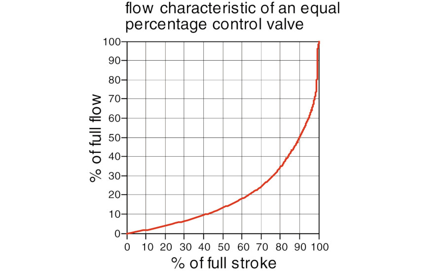
To counteract this non-linear characteristic, many manufacturers offer control valves with "equal percentage" characteristics. The plugs in these valves are shaped so that the gap between the plug and its seat opens very slowly as the stem begins to lift. The farther the stem lifts, the faster the gap between the plug and seat opens.
A typical flow rate versus stem lift curve for an equal percentage valve is shown in Fig. 3. The curve is essentially the mirror image of the heat output versus flow rate curve for the heat emitter. When these two characteristics are paired together, the result is an approximately proportional relationship between heat output and stem lift. This allows the controller to use the full range of stem lift as it varies heat output from 0 to 100%.
> FIGURE 3.
The Don'ts
Don't #1. Don't forget to account for temperature drops along series connected loads. Whenever a stream of water gives up (sensible) heat, its temperature drops. When several loads--be they individual heat emitters or complete secondary circuits--are connected in series along a common piping path, the temperature drop (gT) across each load should be calculated, and then used to determine the supply water temperature available to the downstream heat emitter. Not doing so leads to undersized heat emitters near the end of the circuit.
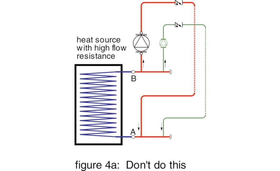
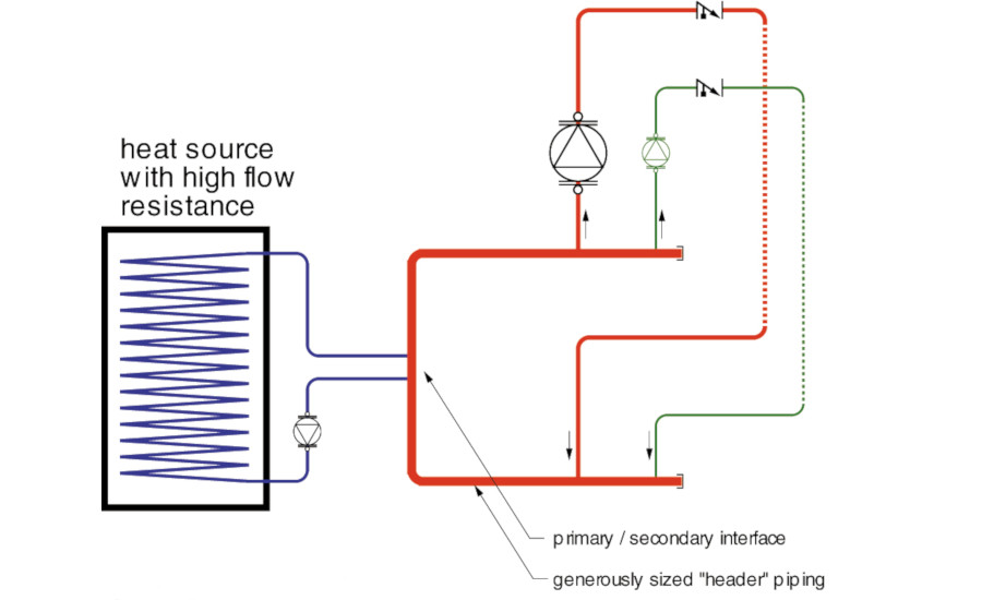
Don't #2. Don't route several independently pumped circuits through a common component having high flow resistance. The situation depicted in Fig. 4a is virtually guaranteed to produce problems. The bigger circulator is capable of setting up a large gP across the high flow resistance heat source. The gP may even be higher than the shut-off head of the smaller circulator, preventing flow in the circuit it serves.
> FIGURE 4a.
To avoid such situations, pipe the high flow resistance boiler to the distribution system using primary / secondary piping, as shown in Fig. 4b. The common (header) piping in a system employing parallel circulators should also be generously sized so that pressure variations along the headers are minimal as various circulators turn on and off.
> FIGURE 4b.
Don't #3. Don't use high head pumps on zone valve systems. Every time a zone valve closes, the system curve gets steeper, and its intersection with the pump curve moves higher. Differential pressure across the pump increases. The "steeper" the pump curve, the greater the incremental rise in pressure as each zone valve closes. A high-head pump with a steep curve can create high velocity flow in piping when only one or two zones are operating. The high gP can even lift the plugs of zone valves that are supposed to be closed, causing heat migration into inactive zones.
Circulators with flat pump curves are best for zone valve systems. If you can't find a circulator with a suitable pump curve, consider pairing up a couple of small circulators in parallel. The curve representing the net performance of parallel circulators becomes increasingly flat as more circulators are added. Still another solution is a variable speed distribution circulator, as mentioned earlier.
Don't #4. Don't short-cycle boilers by "microloading." Think about the thermodynamics of connecting a 150,000 Btu/hr boiler to 15 individual 10,000 Btu/hr loads. The math adds up at design load conditions when all loads are presumed on. But, what happens when only one of those loads is calling for heat? To make matters worse, assume the boiler has very low thermal mass and that relatively little piping lies between the boiler and its load. When the lightly-loaded boiler is fired, its temperature quickly rises to the setting of its limit control, at which time the burner shuts off. Because of the low thermal mass in the system, the temperature of the circulating water drops quickly. Within a minute or two, this classic short-cycle is ready to repeat itself. The end results are poor efficiency and thousands of needless on/off cycles over the course of each heating season. It's only a matter of time until components fail prematurely due to excessive cycling.
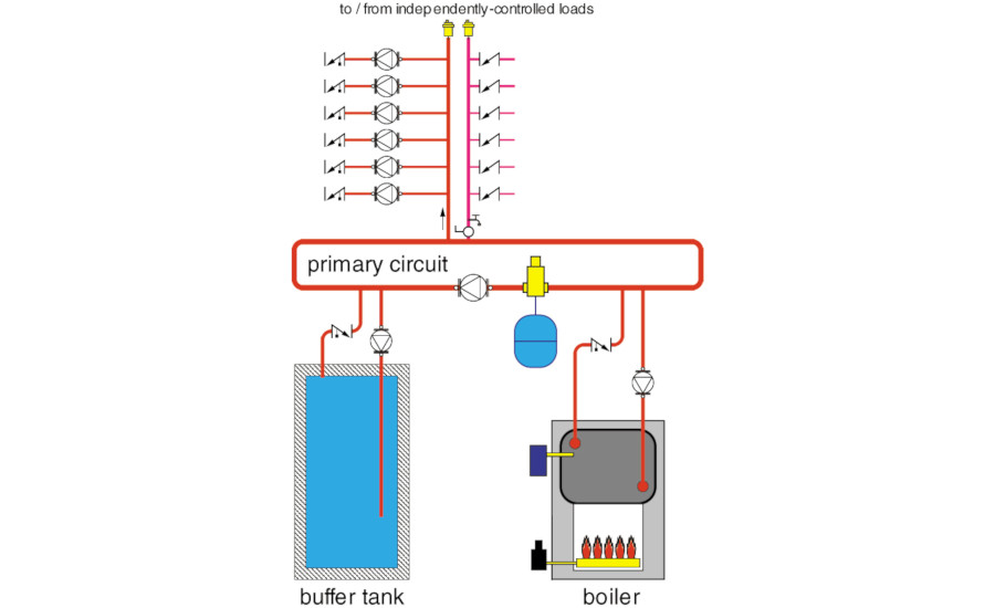
One of two things can correct this situation: 1) a boiler with a modulating burner capable of reducing output as the load decreases, and 2) an insulated buffer tank that acts as sort of a "thermal capacitor" in the system, absorbing the excess heat and allowing the boiler to run for at least a few minutes once it's been fired.
A conceptual piping schematic showing a buffer tank connected as a secondary circuit to the primary loop is shown in Fig. 6. Such piping allows the thermal mass of the tank to go on- and off-line as necessary, depending on the control strategy used.
> FIGURE 6.
Don't #5. Don't oversize control valves. If 2" piping is used for a distribution system, do you automatically specify a 2" control valve? In almost every case, such "line-sized" control valves are at least one pipe size larger than necessary for the application. This is especially true when the valve is used to mix high temperature boiler water to a substantially lower temperature for a radiant floor heating system. In such systems, the amount of hot water required in the mix is usually only of 15 to 20% of the flow rate in the distribution system. A line sized control valve can pass all the hot water needed (even at design conditions) with very little stem movement.
The remaining travel range of the stem is effectively wasted, and accurate control under low load conditions becomes difficult.
Control valves should be selected based on their Cv rating, not their pipe size. It's fairly common to select a control valve with a Cv rating equal to the design flow rate it will handle (in gpm). This yields a 1 psi pressure drop across the valve at design conditions.
Two-way control valves are often used to regulate the heat output of a heat emitter by varying the flow rate through it. Such valves should be selected so the pressure drop across them when fully open is at least half the pressure differential imposed across them when fully closed. Such a valve is said to have an "authority" of at least 50%. Applying a control valve so its authority is at least 50% prevents needless oversizing and allows the valve to modulate over a wide range of stem travel.
Learn Them, Use Them, Enjoy Them
Successful designs demand an understanding and respect for the details and concepts we've discussed. As you sketch out systems, apply them. As you inspect systems, look for their implementation. As you ponder what hardware to specify, use them as a reference. And finally, whenever you get a chance to enjoy the comfort your systems provide, appreciate how they all work together.
