


There are several renewable energy heat sources that can supply some or all of the space-heating load of residential and light commercial buildings when coupled with suitable hydronic distribution systems. Those heat sources include solar thermal collectors, geothermal water-to-water heat pumps, air-to-water heat pumps, as well as pellet-fired, chip-fired, and cordwood-fired biomass boilers.
Optimal performance of these heat sources requires them to be coupled with properly-designed low-temperature hydronic distribution systems.
Several types of radiant panels can provide low-temperature heat delivery, including those located in ceilings and walls, as well as in floors. Other options include “high-output” fin-tube convectors, certain types of fan coils, and panel radiators.
Two or more of these low-temperature heat-emitter options can be combined into the same system. For example, a designer might choose to use heated floors in areas with ceramic tile, along with panel radiators in areas with traditional hardwood floors or carpet. The idea is to select a supply water temperature for design load conditions, and then size the individual heat emitters for the design heating load of the spaces they serve based on a common supply water temperature.
Parallel, not series
To ensure that all heat emitters receive water at the same temperature, it’s essential to use a distribution system with parallel piping “topology.” Ideally, each heat emitter has its own circuit that begins at or near the heat source, passes through that emitter, and goes back to, or near the heat source.
In theory, parallel piping topology can be achieved using just about any piping material. In practice, one of the most practical and easy to install methods is known as a home-run distribution system. Individual segments of small-diameter, flexible PEX or PEX-AL-PEX tubing are routed from a common manifold station to the supply and return connections on each heat emitter. The concept is shown in Figure 1.
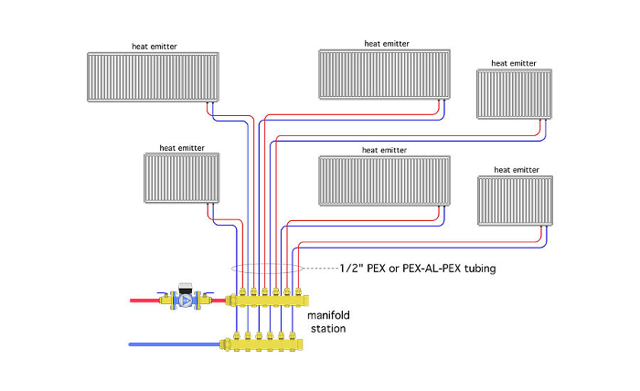
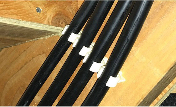
The small flexible tubing used in home-run systems is much easier to route through the framing cavities of buildings compared to any type of rigid piping. In most cases the tubing runs between the manifold station and heat emitter can be continuous, with no need of spices or fittings. The tubing is light enough to pass through enclosed framing cavities without need of support. In accessible areas, the tubing can be supported by small PVC C-clips that are mounted using a single screw (see Figure 2). These C-clips allow the tubing to move slightly as it expands and contracts with temperature changes.
Home-run distribution systems also provide options for balancing the flows between individual heat emitters. One approach relies on a manifold station with integral balancing valves. Another uses the balancing settings built into most thermostatic radiator valves.
There also are options for turning the flow through each heat emitter on and off. One uses 24 VAC valve actuators mounted to the integral valves of the manifold station. The actuators can be wired to thermostats in each space equipped with a heat emitter. When none of the thermostats are calling for heat, the circulator supplying the manifold station can be turned off.
Another option is the use of thermostatic radiator valves on each heat emitter. These valves commonly are used with panel radiators, but they also can be configured for fin-tube convectors and even radiant panel circuits.
Cruise control for Delta-P
Home-run distribution systems ideally are suited to variable-speed pressure-regulated circulators. This type of circulator should be set to a constant differential pressure mode when used in a home-run distribution system. The differential pressure of the circulator should be set to a value that can deliver design flow rate to each heat emitter served by the system, assuming they are all operating under design conditions.
Under partial load conditions the flow required by the distribution system is reduced. The variable-speed pressure-regulated circulator will automatically reduce speed as manifold valve actuators or thermostatic radiator valves partially or fully close. The electrical power demand of the circulator decreases whenever flow rate decreases. This type of circulator also eliminates the need to install a differential pressure bypass valve across the manifold station. At today’s prices it is less expensive to install a high-efficiency variable-speed circulator than it is to install a standard fixed-speed circulator in combination with a differential pressure bypass valve.
Thermal flywheel
A buffer tank provides the thermal mass necessary to stabilize heat sources such as single-stage heat pumps with fixed-speed compressors against the highly variable heat demands of a highly zoned distribution system.
If the heat source is an array of solar thermal collectors, or a biomass boiler, the tank’s buffering function gets extended to provide significant thermal storage. It is possible that the tank would, at times, store several hours worth of space-heating energy. Solar thermal systems typically use one to two gal. of water-based thermal storage per square-foot of collector area. A pellet-fired boiler typically needs one to two gal. of thermal storage per 1,000 Btu/h of rated boiler output. A cordwood gasification boiler requires significant thermal storage, about 130 gal. per cubic foot of primary combustion chamber volume.
Temperature throttle
If the tank provides thermal storage for solar collectors or biomass boilers, it also is possible that it could reach very high temperatures, such as after two or three consecutive sunny days, or at the end of a long burn cycle. If the distribution system has been designed around a much lower supply water it’s imperative to install an automatic mixing valve between the tank and the distribution system. This valve could use a non-electric thermostatic operator, or be operated by a gear/motor actuator. I prefer the latter because it can be controlled based on outdoor reset (e.g., the warmer the outdoor temperature the lower the required supply water temperature).
Put it together
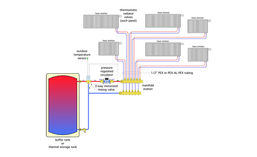
Figure 3 shows all the components and concepts we’ve just discussed assembled into a simple, easy to install, and repeatable configuration that’s an ideal match for many renewable energy heat sources.
Backup: Systems that use renewable energy heat sources, often have auxiliary boilers to supplement or replace the heat output of the renewable heat source. This is especially true for solar thermal systems.
There are several ways to combine an auxiliary boiler with the assembly shown in Figure 3. The preferred method depends on the ability of the boiler to regulate its heat output relative to the heat demand of the distribution system.
If the auxiliary boiler is an on/off device (e.g., non-modulating), and the distribution system is highly zoned, I suggest that the auxiliary boiler be tied into the upper portion of the buffer tank as shown in Figure 4.
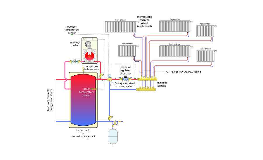
This piping also would be appropriate for a modulating/condensing boiler if its lowest stable rate of heat output is still well above the smallest independently-operated load. It allows the thermal mass in the upper portion of the thermal storage tank to interact with the auxiliary boiler and protects the boiler from short cycling. The sensor in the upper portion of the tank, in combination with the boiler’s internal controller, turn on the boiler when the temperature drops below an acceptable minimum value for space heating. The boiler remains on through a reasonable temperature rise of perhaps 10 to 15° F at the tank sensor.
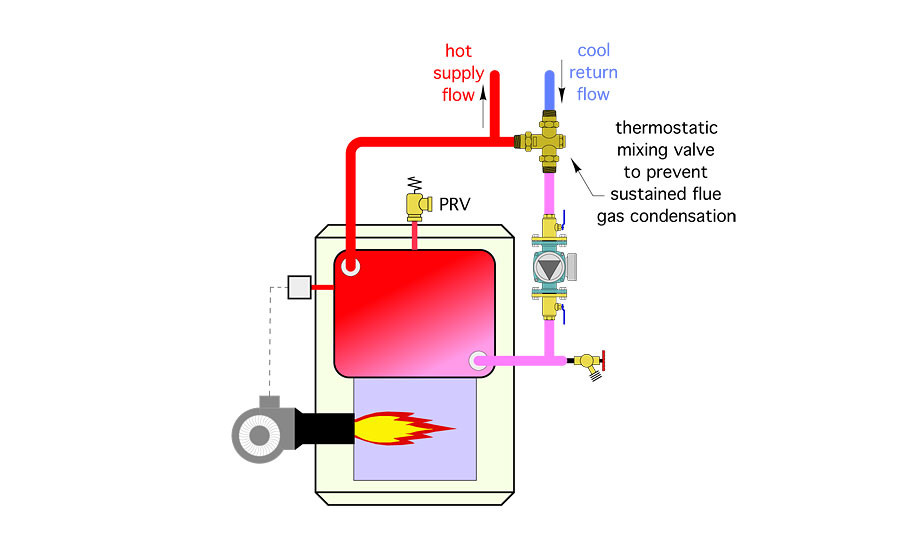
If a conventional boiler is used (e.g., a boiler not designed to operate with sustained flue-gas condensation), and the distribution system is designed around low-water temperature, it’s important to include an anti-condensation mixing valves on the boiler as shown in Figure 5.
If the auxiliary boiler can reduce its heat output to reasonably match the lowest independent-zone load, it can be piped “downstream” of the buffer tank as shown in Figure 6.

Sophistication doesn’t imply complication. The synergy of the sub-systems discussed is sophisticated but not complicated. They provide modulated heat delivery using very little hydraulic power. The components for creating these sub-systems are readily available from several North American suppliers. Keep them in mind for your future renewable energy heating projects.
This article was originally titled “Hydronics heaven” in the April 2017 print edition of PM Engineer.


