

The Second Law of Thermodynamics implies it’s not wise to convert high-grade energy, such as the chemical energy in a fuel, into lower-grade thermal energy until the latter is needed. The chemical energy in most fuels can be stored for years. However, once that energy is converted into heat, it’s a race against time to contain it.
The insulation of the container and temperature difference between the heated material in the container and the materials outside the insulation system determines the pace of the race. In the end, higher temperature always yields to lower temperature and the usefulness of the original energy continually diminishes.
Still, when designing heating systems, there are considerations other than the Second Law of Thermodynamics. One of them is attaining good thermal efficiency from a combustion-based heat source. When combustion is involved, long operating cycles where steady-state conditions prevail is desirable. Unfortunately, when a boiler is oversized for design load and connected to a highly zoned distribution system, steady-state conditions are rare occurrences. Instead, “short cycling” becomes the modus operandi of the heat source.
Short cycling is something to avoid in new systems. It’s also something that should be corrected when an existing system is expanded or otherwise significantly modified.
When a pellet boiler is added to an existing heating system containing multiple zones of low thermal mass heat emitters, a thermal storage tank containing 1 to 2 gal. of water per 1,000 Btu/hr. of pellet boiler output is crucial in avoiding short cycling.
In last month’s column we looked at a system where a pellet boiler was added to a system with an existing boiler which became referred to as the auxiliary boiler. The system is supposed to use heat from the pellet boiler whenever possible and only bring on the auxiliary boiler for peak loading or if the pellet boiler is offline for maintenance.
We also looked at a simple way to prevent heat generated by the auxiliary boiler from inadvertently entering the thermal storage tank associated with the pellet boiler. The rationale was the Second Law principle of not converting high-grade energy (e.g., the chemical energy in the fuel for the auxiliary boiler) into lower-grade energy (e.g., heat) until the latter was needed by the distribution system.
Different circumstances
What about a situation where the existing boiler is well oversized for the load and already is short cycling? Information gathered in programs where pellet boilers have been incentivized has found it is common for an existing boiler to be significantly oversized for the building’s design heating load as determined by a current ACCA Manual J heating load estimate.
This implies the existing boiler will continue to short cycle, especially when it’s only supplementing the output of the pellet boiler.
How could such a situation be remedied?
One solution would be to replace the existing boiler with one that’s appropriately sized for the dual-fuel system. It’s a nice thought, but it’s rarely done due to cost.
Another approach would be to add a separate buffer tank for the auxiliary boiler. This would help, but it’s also costly and requires more space in the mechanical room. It also adds to standby heat loss, and unless the new buffer tank is maintained at useful temperature whenever it might be needed, increases the time delay between when heat is needed and when it can be delivered from the auxiliary boiler.
Shared mass
A more creative approach is to recognize there’s going to be a thermal storage tank added to the system for the pellet boiler. Why not “borrow” some of the thermal mass of that tank to buffer operation of the oversized and short-cycling auxiliary boiler?
Yes, this does depart from the concept of not adding heat to thermal storage from the auxiliary boiler as discussed in last month’s column. But it’s a compromise that may lead to better overall system performance, especially when the opportunity is at hand to remedy an existing problem as part of the system “makeover.”
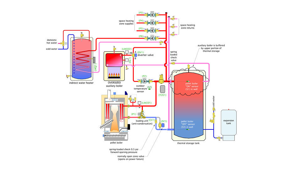
Figure 1 (see above) shows one way to approach this.
The auxiliary boiler is piped between the upper left-side header and the upper right-side connection of the thermal storage tank. When the auxiliary boiler is operating and the diverter valve (DV1) is not powered, flow from the auxiliary boiler passes from the diverter valve’s “AB” port to the “B” port through circulator (P2) and into the upper-left header of the thermal storage tank. Some of this flow will be pulled into any active zone circuits. The rest flows into the thermal storage tank.
The exact amount of “interaction” between the water in the upper portion of the thermal storage tank and the auxiliary boiler is determined by the height of the tank connections, the entering flow velocity and the position of sensor (S1) within the tank.
The goal is to allow sufficient interaction with the tank’s thermal mass to prevent the auxiliary boiler from short cycling while still leaving most of the thermal storage tank’s volume to absorb heat from the pellet boiler.
A typical residential cast-iron boiler containing 350 lb. of cast iron and 10 gal. of water has a thermal mass of about 122 Btu/Fº. If that boiler interacted with 20 gal. of water in the thermal storage tank, the combined thermal mass increases to 289 Btu/Fº. That 20 gal. would only be 20% of a 100-gal. thermal storage tank associated with a 50,000 Btu/hr. pellet boiler. While I can’t give you an exact percentage of the thermal storage volume that’s necessary in every case, these numbers show that even 20 gal. adds significant buffering for a typical residential boiler.
Details are important. This scenario relies on temperature stratification within the tank. Be sure flow entering the upper portion of the buffer tank does not create vertical flow jets. High sidewall connections with generous pipe sizing to reduce entering flow velocity are advisable. The vertical position of sensor (S1) also will determine how much water in the thermal storage tank interacts with the auxiliary boiler. If that sensor is mounted in a vertical well, the length of that well could be changed to alter the buffering effect. The lower the sensor is in the tank, the greater the amount of water that will interact with the auxiliary boiler.
Summer mode
It’s possible heat from the pellet boiler could be used year-round for domestic water heating. However, for the system in Figure 1 this would require the thermal storage tank to remain at a relatively high temperature year-round. It also keeps the upper portion of the thermal storage tank interacting with the thermal mass of the indirect water heater circuit whenever there’s a call for domestic water heating.
One option is to set up the system so the pellet boiler can be turned off in summer. The auxiliary boiler then becomes the sole heat source for domestic water heating. The thermal mass of the indirect water heater is sufficient to stabilize the auxiliary boiler against short cycling. Thus, if the pellet boiler if off during the summer, there’s no need to involve the thermal storage tank in the process.
This is done by installing a diverter valve in the auxiliary boiler flow path. During heating season operation the diverter valve is not powered. It directs all flow leaving the auxiliary boiler from its “AB” port to its “B” port and toward the upper-left header on the thermal storage tank. In summer, the diverter valve is powered on and directs flow from the auxiliary boiler to the indirect water heater or a space-heating zone if it happens to be on. The necessary control logic is handled by a triple-pole double-throw switch, which is shown as part of the electrical schematic in Figure 2 (see above).
The following is a description of operation for the system shown in Figures 1 and 2.
System power: The master switch (MS) must be closed to provide 120/24 VAC power to the control system and to the multi-zone relay center (MZRC). The 2-stage reset controller (T261) is powered on as soon as the master switch (MS) is closed. The pellet boiler is supplied through a dedicated 120 VAC/20 amp circuit. The low-water cutoff (LWCO1) must detect water and the pellet boiler disconnect (PBD) must be closed for 120 VAC to reach the pellet boiler. The auxiliary boiler is powered through another dedicated 120 VAC/20 amp circuit. The low-water cutoff (LWCO2) must detect water and the auxiliary boiler disconnect (ABD) must be closed for 120 VAC to reach the auxiliary boiler.
Winter mode: The mode selector switch (MSS) is set for winter. This supplies 24 VAC to the heating demand terminals of the (T261) two-stage reset controller and powers up the temperature setpoint controller (SP1). The (T261) measures outdoor temperature at sensor (S2) and uses this temperature along with its settings to calculate the minimum allowed temperature at tank sensor (S1). It then compares the calculated minimum allowed temperature to the current temperature of sensor (S1). If the measured temperature is slightly below the minimum allowed temperature, the stage 1 contacts in the (T261) controller close. This passes 24 VAC to the coil of relay (R2). Contact (R2-1) closes to provide a heat demand to the pellet boiler. The pellet boiler initiates its combustion sequence and passes 120 VAC to circulator (P1) in the loading unit to create flow between the boiler and thermal storage tank. The loading unit recirculates boiler water until the return temperature to the pellet boiler climbs above 130º, at which point the loading unit starts allowing hot water flow from the boiler to the thermal storage tank.
The stage 1 contacts in the (T261) will open when the temperature at sensor (S1) climbs a few degrees above the target temperature. However, the contacts in the setpoint controller (SP1) will be closed because the temperature in the lower portion of the thermal storage tank is less than 165º. This provides an alternative path for 24 VAC through relay contact (R2-2) to maintain relay coil (R2) energized until the lower tank temperature at sensor (S3) reaches 175º, at which point the contacts in the setpoint controller (SP1) open, breaking 24 VAC to relay coil (R2) and turning off the pellet boiler and circulator (P1).
If heat input from the pellet boiler is unable to achieve and maintain the minimum allowed water temperature at sensor (S1), the stage 2 contacts in the (T261) controller close within a short time. If there also is a demand from any of the space-heating thermostats or aquastat (AQ1), a circuit is completed through the stage 2 contacts of the (T261) and the (X X) contacts of the multi-zone relay center (MZRC) across the (T T) terminals in the auxiliary boiler’s high-limit controller. This enables the auxiliary boiler to fire if its water temperature is slightly below a setpoint of 180º. The auxiliary boiler turns on circulator (P2) whenever there is a demand on the (T T) terminals. Heated water from the auxiliary boiler flows from the AB to B ports of the diverter valve (DV1) to the upper-left header of the thermal storage tank. Some of this flow passes to any active zone load, the rest passes into the thermal storage tank. Return flow to the auxiliary boiler is from another connection on the opposite upper side of the thermal storage tank. If there is no demand from a space-heating zone or the indirect water heater, the auxiliary boiler cannot fire.
Domestic water heating (winter mode): If aquastat (AQ1) closes indicating a demand for domestic water heating, circulator (P6) and relay coil (R1) are powered on by 120 VAC delivered through the multi-zone relay center (MZRC). Relay contact (R1-1) closes to provide a setpoint demand to the (T261) controller. When this occurs, the (T261) targets a fixed temperature of 150º at sensor (S1) regardless of outside temperature. It then attempts to achieve this temperature, when necessary, by first closing its stage 1 contacts and, if necessary, the stage 2 contacts as described in the preceding paragraph.
Summer mode: The mode selection switch (MSS) must be set to summer. This passes 24VAC to diverter valve (DV1), which actuates to open the flow path from the AB to A ports and blocks the flow path from the AB to B ports. The mode selection switch (MSS) in summer mode prevents 24VAC from reaching the stage 1 contacts of the (T261) controller. It also electrically isolates the stage 2 contacts and circulator (P2). If any space-heating thermostat of aquastat (AQ1) calls for heat, the (X X) terminals in the (MZRC) close, providing a demand to the auxiliary boiler, which fires if its water temperature is slightly below 180º. Heat flows from the auxiliary boiler to any active zone circuit. No heat is added to the thermal storage tank in this mode. The pellet boiler, as well as circulators (P1) and (P2), cannot operate in this mode.
Pellet-fired boiler overheat protection: There must be an uninhibited flow path between the pellet boiler and thermal storage tank during a power outage. This allows residual heat from burning pellets to be dissipated into thermal storage. However, there should not be heat migration through the pellet boiler when it is off and heat is being supplied by the thermal storage tank. The combination of a spring-loaded check valve (CV1) with a forward-opening pressure of at least 0.5 psi and a normally-open zone valve (ZV1) provide these two functions. (ZV1) will be closed whenever utility power is available to the system and master switch (MS) is closed. The forward opening resistance of check valve (CV1) provides sufficient resistance to block heat migration through the pellet boiler whenever circulator (P1) is not operating. However, during a power outage (ZV1) opens to provide a “detour” around check valve (CV1), thus allowing thermosiphon flow between the pellet boiler and thermal storage.
Controller settings
The most common existing system to which a pellet boiler is retrofitted has high-temperature heat emitters such as fin-tube baseboard or fan coils. These heat emitters often are sized based on a supply water temperature in the range of 180º at design load.
Existing systems also usually are supplied by conventional boilers (e.g., boilers that are not intended to operate with sustained flue-gas condensation). The burner on these boilers usually is fired by a high-limit controller with a fixed temperature setting. Typical operating conditions might be: Burner on at 175º and burner off at 185º.
The water temperature supplied to high-temperature heat emitters can be reduced during partial load conditions using outdoor reset control. For example, a system with a design load supply temperature of 180º at a corresponding outdoor design temperature of 0º, could theoretically supply 50% of design load output when supplied with 125º water. This implies the minimum allowable temperature at sensor (S1) can be reduced well below design load conditions on a part-load day. The graph in Figure 3 (on page 18) shows a possible scenario.
If the existing boiler is not protected against sustained flue gas condensation, which is the common scenario, a suggested minimum allowable temperature for sensor (S1) is 130º. This lets the auxiliary boiler operate, when necessary, at conditions that prevent sustained flue-gas condensation.
If the existing boiler is retrofit with a thermostatic boiler protection valve as shown in Figure 3, the minimum allowable temperature at sensor (S1) can be lowered. This lets the thermal storage tank cycle over a wider temperature range, which increases pellet boiler runtime and improves its efficiency.
Figure 3 also shows the minimum allowable temperature at sensor (S1) during a call for domestic water heating is a fixed 150º regardless of outdoor temperature. The pellet boiler “OFF” temperature for the lower tank sensor (S3) is a constant 175º.
Remember, the piping and control concepts discussed are intended to remedy short cycling of an existing boiler when retrofitting a pellet boiler and thermal storage to the system.
When the designer has the prerogative of selecting the auxiliary boiler rather than working around an existing boiler, that boiler should be sized based on an up-to-date heat load estimate for the building. Its rated output should never exceed the building’s current design load.
In some circumstances it’s even reasonable to select an auxiliary boiler with a rated output that’s smaller than design load, since its intended role is to supplement the pellet boiler. A modulating auxiliary boiler also is preferable when feasible, especially where the distribution system has several zones. When the auxiliary boiler can be selected rather than “inherited,” there is seldom need to buffer it using the thermal storage tank.
This article was originally titled “Beneficial buffering” in the January 2017 print edition of PM Engineer.


