


With the right design, geothermal heat pumps can work in a variety of applications.
The HVAC trade spotlight continues to shine on geothermal heat pump systems in buildings ranging from single-family homes to large commercial facilities.
The geothermal heat pump industry has organized regional and national trade associations that advocate for the use of these systems with outreach to consumers and lobbying efforts with politicians. These days, you can expect to read about geothermal heat pump applications in just about any forum that deals with HVAC technology.
One specific type of heat pump, known as a water-to-water heat pump, can provide the bridge between geothermal energy and the unsurpassed comfort that is possible through hydronic radiant panel delivery systems.
My firm has designed several systems around such heat pumps. Many of the inquiries we receive from potential clients reveal a predisposition toward the use of geothermal heat pumps in upcoming projects.
Geo +
Although it’s possible to size a geothermal heat pump to provide the full design heating requirement of a house or small commercial building, there are other options. One that lends itself well to modern hydronics technology is to combine the heat pump with a boiler. This is often called a “dual fuel” approach, and there are several benefits associated with it.
First, a dual-fuel system provides the security that one heat source can cover some of the heating load if the other heat source is out of service.
Next, the heat pump can be sized to less than the design heating load of the building. This may be necessary due to limited land area for installation of the earth loop. It also may be necessary in situations where earth loop installation costs are high.
Third, having a heat pump and boiler that can operate simultaneously allows for high heat delivery rates that can speed recovery from thermostat setbacks, as well as provide higher domestic water heating recovery rates when necessary.
Finally, in some locations utilities offer steeply discounted “time-of-use” electrical energy prices during periods of low demand. These rates can significantly reduce the operating cost of a heat pump during off-peak hours while allowing a gas-fired boiler to meet demand during “on-peak” periods when electrical rates are significantly higher. Controls can be configured to operate the heat pump as the first stage of heat generation, or the only stage of heat generation, during these off-peak periods.
Lower is better
Most geothermal water-to-water heat pumps can only supply water at temperatures in the range of 120° to 125º F without experiencing significant decreases in their coefficient of performance, as well as their heating capacity. Because of this, I recommend any hydronic distribution system supplied by a heat pump be designed so it can provide the design heating requirement of the building using a supply water temperature no higher than 120º. This allows for good performance from the heat pump as well as condensing mode operation (e.g., high efficiency) from a mod/con boiler in a dual-fuel system.
One type of hydronic distribution system that meets this requirement is a radiant ceiling panel. When properly designed, a low-mass radiant ceiling, constructed as shown in Figure 1, can provide an output of 28 Btu/hr./ft2 when operated at an average water temperature of only 110º. This could correspond to a supply water temperature of 120º and a return water temperature of 100º under design load conditions. Even lower supply water temperatures are possible under partial load conditions.
The downward heat output of the radiant ceiling panel shown in Figure 1 also can be estimated for other operating conditions using Formula 1.
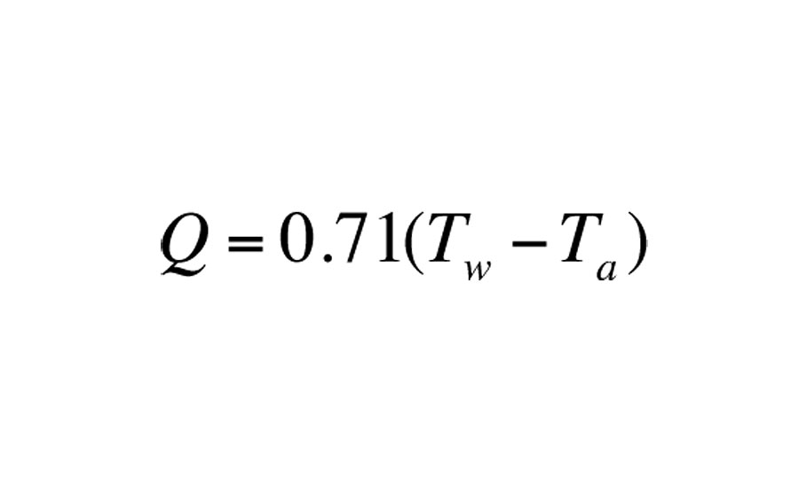
Q = rate of downward heat output (Btu/hr/ft2)
Tw = average water temperature in circuit (ºF)
Ta= room air temperature (ºF)
Boilers don’t chill
One of the major benefits of having a water-to-water heat pump in the system is that it can supply chilled water for cooling. Indeed, the requirement for building cooling is often what sways the design toward a heat pump rather than a “heating-only” heat source such as a boiler.
The classic approach to chilled water cooling uses one or more air handlers equipped with condensate drip pans. These air handlers provide both sensible and latent cooling. The condensate that forms on the air handler’s coil as a result of latent cooling falls into a drip pan under the coil and is drained away.
Over the last few years a new “form factor” for small hydronic air handlers has emerged. This new design is called a high-wall hydronic cassette. An example is shown in Figure 2.
This air handler looks like the high-wall cassettes used in “ductless” heat pump or VRF systems. The difference is it is supplied with heated water or chilled water rather than refrigerant. That water can usually be supplied through 1/2-in. PEX tubing that has been insulated to prevent condensation. The unit contains a drip pan and insulated drainage tube that collects condensate during chilled water cooling operation and routes it to a suitable drain.
The cassette shown in Figure 2 is operated by a handheld remote. It can be configured for cooling, heating, dehumidification or fan-only operation. It has a quiet variable-speed blower and motorized louvers that smoothly spread the discharge air stream over a wide area of the room. Two or more cassettes easily can be configured into a multi-zone chilled water cooling system.
Putting it all together
Figure 3 shows the piping schematic for a dual-fuel system that provides space heating using radiant ceiling panels, cooling using chilled water air handlers and year-round domestic water heating. The DHW load is sourced from both the desuperheater in the heat pump and the boiler.
During heating mode, the heat pump and mod/con boiler can supply heat to the buffer tank, individually or together, depending on the load requirement. Given the unit cost of heat from the heat pump is usually lower than that from the boiler, the heat pump provides first-stage heat input with the boiler “taking up the slack,” as necessary, to ensure the water temperature in the tank is adequate to supply the space-heating load.
This is all coordinated by a two-stage outdoor reset controller that monitors the water temperature in the tank. The warmer it is outside, the lower the necessary buffer tank temperature. This outdoor reset logic maximizes the performance of both the heat pump and boiler by only heating water to the temperature necessary to satisfy the current space-heating load.
The heat pump’s desuperheater adds heat to the domestic water in the lower portion of the indirect water heater whenever the heat pump is running. The boiler provides supplemental heat to the indirect water heater when necessary. In cooling mode operation, any heat supplied to domestic water by the desuperheater is heat that would otherwise be dissipated into the earth loop. This is truly “free heat” given the alternative of dumping those Btu into the ground.
The distribution system consists of zoned manifold stations that supply radiant ceiling circuits. Two manifold stations are shown, but more could be added if necessary. Flow to each manifold station is allowed or prevented by a standard zone valve. The pressure-regulated circulator automatically adjusts its speed as the zone valves open and close. The air handlers are shown “grayed out” based on the assumption they do not operate in space-heating mode.
Figure 4 shows the same system during cooling mode operation.
The heat pump supplies chilled water to the buffer tank and to the chilled water air handlers. The piping details shown near the buffer tank allow some of the chilled water from the heat pump to go directly to the air handlers when needed. If the chilled water flow rate from the heat pump exceeds the flow rate to the air handlers, the difference in flow rates enters the buffer tank. The “short and fat” header piping that connects to the tank allows it to provide hydraulic separation between the heat pump circulator (P2) and the variable-speed distribution circulator (P3).
During cooling mode, the heat pump is operated based on the chilled water temperature in the buffer tank. A typical control criterion is to operate the heat pump as necessary to maintain this temperature between 45 and 60 ºF. This is done using a simple temperature set-point controller.
Heat from the pump’s desuperheater, as well as supplemental heat from the boiler again are routed to the indirect domestic water heater.
Systems that merge the thermal efficiency of a geothermal heat pump, the on-demand reserve power of a mod/con boiler, the versatility of zoned chilled water cooling and the heating comfort of hydronic radiant panels can provide unique thermal solutions for a wide range of buildings.
Perhaps it’s a combination you should consider for an upcoming project.
This article was originally titled “Covering all the bases” in the December 2015 print edition of pme.


