
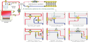
There are many options for mixing in hydronic systems and they can be categorized as follows:
- Valve-based mixing with two-way thermostatic injection valves; 2-way motorized mixing valves; 3-way thermostatic mixing valves; 3-way motorized mixing valves; 4-way motorized mixing valves.
- Pump-based mixing with on/off injection pump; variable-speed injection pump; direct-injection piping; and reverse-injection piping.
Figure 1 shows how several of these options can be piped to create a “mixing assembly” between a conventional boiler and a low-temperature distribution system.
|
|
FIgure 1. Click here to see larger image. |
The mixing assembly can be thought of as a “heat bridge” between the boiler loop and distribution systems. All heat that passes from the boiler loop to the distribution system must cross this bridge. With proper control, the rate of heat transfer through the mixing assembly can range from zero, to the full-rated output of the boiler.
When configured as shown in Figure 1, each mixing assembly will provide two important functions:
1. Create an appropriate supply water temperature for the distribution system.
2. Raise the boiler inlet temperature sufficiently high to prevent sustained flue- gas condensation.
In the early days of radiant-panel heating in North America, the latter function was thought to be of secondary importance. From a controls perspective, the focus was on creating the proper supply water temperature, especially when mixing was combined with outdoor reset control.
This prioritizing of supply water temperature control over boiler protection quickly proved to be shortsighted. Many conventional boilers constructed with cast-iron, steel and copper-tube heat exchangers succumbed to the corrosion and scaling associated with sustained flue-gas condensation. Ditto for the galvanized-steel vent piping used to connect these boilers to chimneys.
Hindsight led to improved control offerings that ensured such boilers would not be operated with sustained flue-gas condensation. Today, most, but unfortunately not all, hydronic system designers understand both control functions are vital in systems that pair conventional boilers with low-temperature distribution systems.
Protection against sustained flue-gas condensation also is vitally important with wood-fired boilers. If such boilers operate with low entering water temperature, some of the pyrolytic gases released during combustion will condense and eventually solidify on the inner surfaces of the combustion chamber, heat exchanger, vent connector and chimney. The result is creosote – a dark-gray, tar-like substance that has significant flue value if ignited. Such ignition can create extremely dangerous chimney fires. Creosote accumulation within the boiler also reduces heat transfer efficiency.
Boiler protection options
There are several ways to protect a wood-fired boiler from such a condition including:
- 3-way thermostatic mixing valves;
- Loading units (thermostatic valve combined with circulator);
- 3-way motorized valves; and
- On/off shuttle circulators.
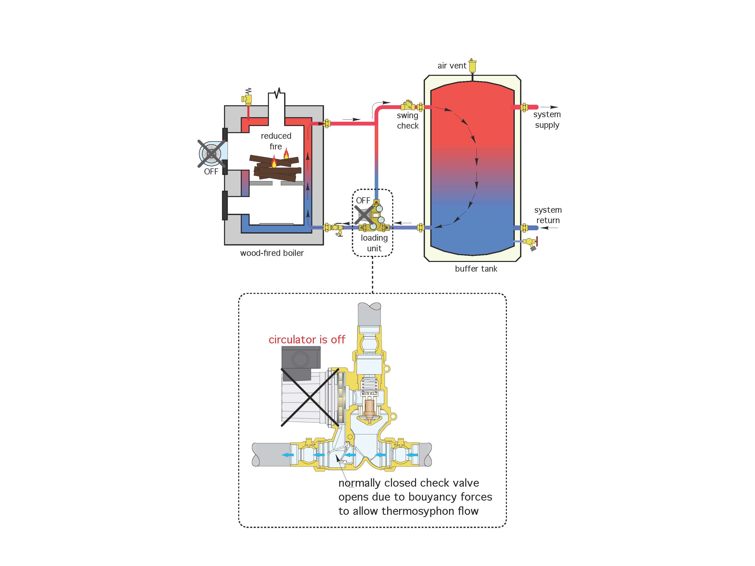
Of these, the use of loading units and motorized 3-way mixing valves are most common. Loading units combine a 3-way thermostatic valve with a circulator and flapper check valve. The latter allows thermosiphon flow between the boiler and thermal storage tank during a power outage. This function is most important in boilers that burn cordwood or wood chips, vs. those that burn pellets because of the potential amount of unburnt fuel in the combustion chamber at the onset of a power outage. Boilers that burn wood pellets have relatively low amounts of fuel in the chamber at any given time and thus the amount of residual heat that must be dissipated is small.
Figure 2 shows an example of a loading unit installed between a wood- gasification boiler and thermal storage tank.

|
| Figure 2. Click here to see larger image |
The operating mode shown in Figure 2 assumes electrical power is not available. Hot water from the residual combustion in the boiler is flowing from the boiler to the thermal storage tank by thermosiphoning. The internal flapper valve inside the loading unit opens to allow thermosiphon flow because the normal pressure differential created by the circulator in the loading unit is not present.
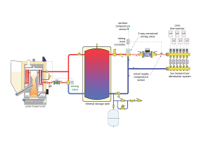
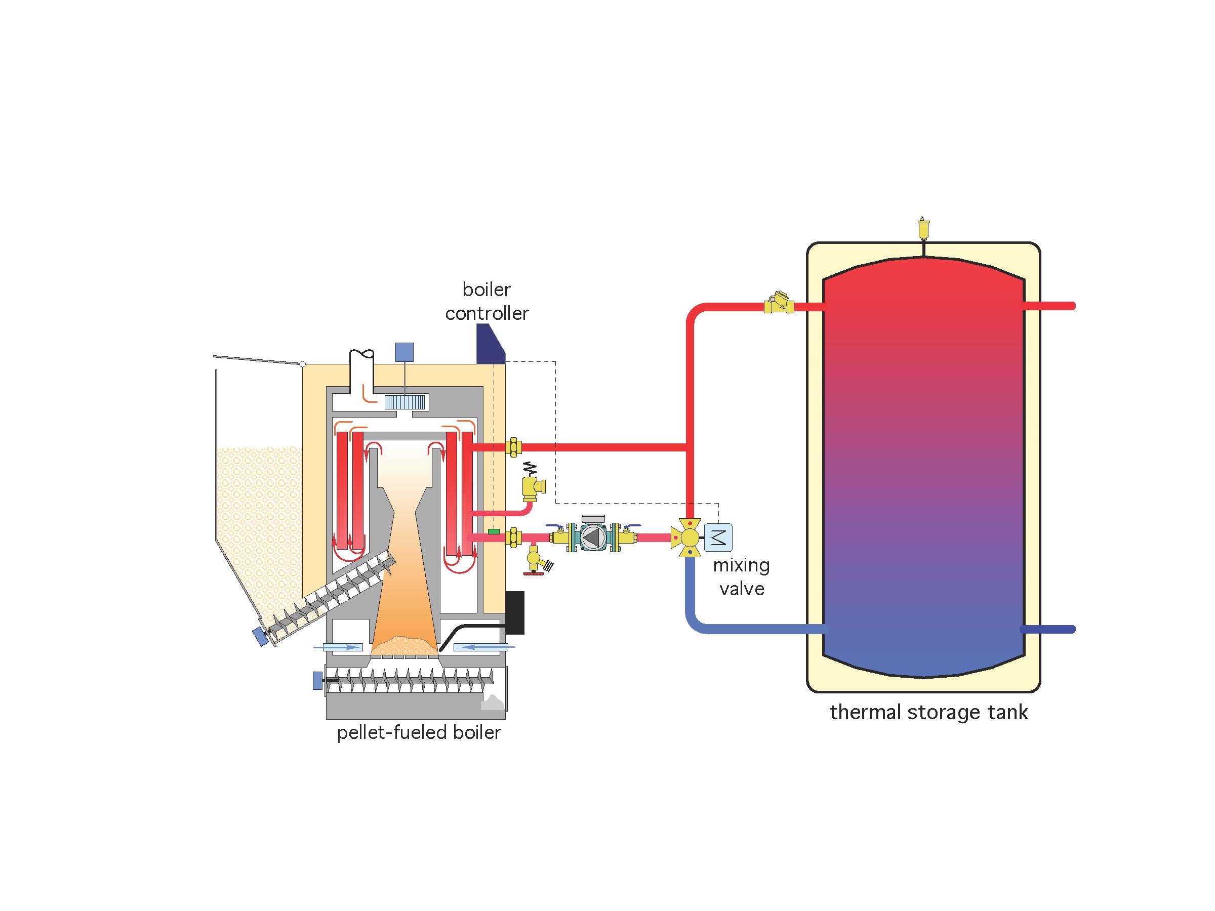
Many state-of-the-art wood-fired boilers, especially pellet-fired and chip-fired boilers of European design, use a motorized 3-way valve, installed as shown in Figure 3, to protect the boiler from sustained flue-gas condensation.
The logic to operate the 3-way motorized valve is typically embedded in the controller that operates the boiler. Some of these boilers are even shipped with the required 3-way motorized valve.
The operating logic is based on the temperature of water entering the boiler. A user-defined minimum entering water temperature is set on the controller. It’s typically in the range of 130º to 140º F depending on the moisture content of the wood used in the boiler and the air/fuel ratio. When t

|
| Figure 3. Click here to see larger image. |
he boiler starts from a cool condition, the 3-way valve routes all water leaving the boiler back into the boiler’s inlet. No hot water is allowed to flow to the thermal storage tank. This allows the water temperature in the boiler to increase as quickly as possible and thus minimizes the time under which intermittent flue-gas condensation occurs.
When the inlet temperature to the boiler rises above the set minimum, the 3-way valve modulates to allow some water flow between the boiler to the thermal storage tank. When the inlet water temperature is several degrees above the minimum, all water leaving the boiler is routed to storage, and all water returning from storage goes direct back to the boiler. No mixing occurs during this condition.
Aim low
To maximize the performance potential of a biomass boiler, it’s important to match it with an appropriate distribution system. Distribution systems that can operate at low water temperatures are well-suited for such applications.
This is not because biomass boilers are incapable of higher water temperatures. Indeed, most wood-fired biomass boilers can operate at temperatures up to at least 200º F. The reason for low-temperature distribution systems is to allow the widest possible temperature range on the thermal storage tank. For example, a tank that can operate from an average high temperature of 200º F down to an average, but still useable, temperature of 110º F, can store 50% more heat than the same tank matched to a distribution system that only meets design load if its average temperature remains above 140º F.
My suggestion is to design all distribution systems that will be used with biomass boilers so they can supply design load output using a supply water temperature no higher than 120º F. Combine this approach with outdoor reset control to regulate the supply water temperature even lower under partial-load conditions.
Load-side mixing
When a low-temperature distribution system is supplied from a thermal storage tank that, at times, also will be a relatively low temperature, mixing options become more limited. Three-way thermostatic valves are not well-suited because they don’t allow for automatic outdoor reset control, and 4-way motorized valves are not needed because it’s not necessary to provide a minimum inlet temperature to the thermal storage tank.
Injection mixing using a pump or 2-way valve is theoretically possible, but when the temperature of the thermal storage tank is low, the required injection flow rate to meet design load will be significantly higher than it would be when the heat source operates at a consistently high temperature. This will require an injection pump that operates at high input power or a large 2-way injection valve.
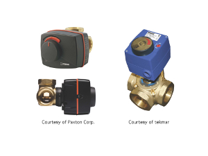
Rotary-type 3-way motorized mixing valves are well-suited to the required operating conditions in this type of system. They provide high range options, relatively low head loss and can be easily configured to operate with an outdoor reset controller. Figure 4 shows two examples of such valves, both configured with motorized actuators.
|
|
Figure 4. Courtesy of Paxton Corp. and tekmar. Click here to see larger image. |
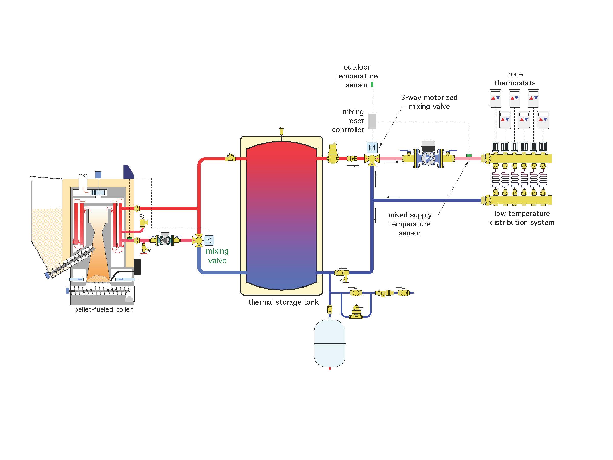
Figure 5 shows a system that uses a pellet-fired boiler supplying a low- temperature distribution system. The boiler’s internal controller operates a motorized 3-way mixing valve for boiler protection. A second motorized 3-way valve provides load- side mixing using outdoor reset control.
|
| FIgure 5. Click here to see larger image. |
The thermal storage tank provides buffering forthe highly-zoned low-temperature distribution system. It also provides hydraulic separation between the boiler circulator and variable-speed, pressure-regulated circulator in the distribution system.
A swing check valve is installed near the upper left inlet connection to the thermal storage tank. It’s there to stop reverse thermosiphoning of heated water through a partially open mixing valve when the boiler is not operating. A spring-loaded check valve is installed on the upper right tank outlet to prevent forward thermosiphoning when the distribution system is off.
This system is a good example of how modern hydronic technology can be used to complement (rather than conflict with) the operating characteristics of biomass boilers.
Such systems can provide unsurpassed comfort while also making the most efficient use of a highly renewable and readily available fuel source.

